Rack and pinion drive system
of the ornithopter model EV7
1. Drive unit
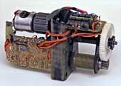
The required input power for the drive motor calculated in 1986 for inclined climb was an average of 133 watts and a maximum of 211 watts during a flapping period.
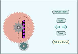
2. Animation of the rack and pinion system
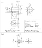
There was used a pin rack with a pitch of 6 mm. Corresponding chain drives are used at model cars. This rack moves up and down and drives the inner lever of the flapping wing.
The rotating pinion must be leaded along the black dotted line around the rack.
First the power flight must be switched on. To go back to gliding flight at any time a short click on the gliding flight button is enough. In the following round passing the lower dead point the motor will be reduced to half speed and gets switched off to gliding flight position.
Note:
- The Adobe Flash Player would be required to operate the shown rack and pinion drive system. However, this is no longer to be used. Therefore, when clicking on the image, only an animation is displayed (to operate the Rack and pinion drive system without Flash Player, please see related link 1).
3. Drive mechanism
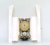
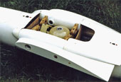
The gas pressure spring for storing the aerodynamic upstroke energy and balance the lift forces is good to be seen. A pressure vessel with the valve of a bicycle is like the driving mechanism of the EV4. Also visible is the small cover for the steel spring at the final wing stroke positions. For the flow of energy in the springs please look at the handbook, chapter 1.5, 1.6 and 2.5, also 5.2 and 5.3.
The wing stroke was controlled by linkages over the 55 mm long lever arms of the wing adapter rollers.
3.1 Drawings of the driving mechanism
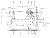
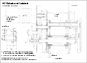
Longitudinal section drawing through the fuselage
with a view to the area of the drive mechanism. The drawing shows in particular
the swing (Sch) in the side view with its built-in components. Furthermore
is shown the location of the gear mechanism (AW, Z1, Z2) with its sprocket
pinion (TR) in relation to the pin rack.
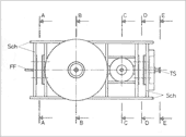
Top view to the swing
The swing
is a frame of plywood with attached components of the drive.
The frame is hanging on the levers like a swing.
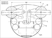
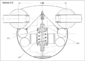
Cross section through the fuselage at the linkages of the wing adapter rollers. The lever (L) connected the swing (Sch) with the inner lever arm (F) of the wing adapter roller (W) or the wing. For reinforcing the fuselage on both sides are glued two carbon tubes (R). They are tapered fore and aft to the inner surface of the fuselage.
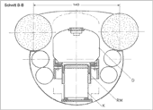
Cross section through the fuselage at the compensating spring
During gliding flight the lift affects an upward directed torque of the wing.
The compensating spring
compensated or balanced this torque on the
inner lever arm of the wing. But the lift during the upstroke is smaller and
during the downstroke larger than at gliding flight (please look at calculation
tool Orni 1
). So, in flapping flight
with a compensating spring the motor must develop the difference of the torques
between gliding and flapping flight. But this difference is relatively small.
In this way the motor is less and relatively equally loaded during the whole
stroke cycle.
Furthermore, the compensating spring assists the adjustment and compliance of the glide position of the wing during the flight. Also, depending on the settings of the spring it enables to adjust different length of the cycle time of upstroke and the cycle time of downstroke. In addition, in it you can buffer the energy of the wing upstroke.
Here, the spring is designed as an inflatable or adjustable gas spring. It works with an average operating pressure of about 3.2 bar [320 kPa] and has an elastic force of 460 N. The maximum permissible pressure is 5 bar.
The rolling diaphragm (RM) is used as a seal between the piston (K) and the cylinder. It works with low friction and it is clearly visible in the adjacent drawing.
The pressure-vessel (D) I have made of fibreglass reinforced epoxy resin over a mould of candle wax (please take a look at the pencil drawings, PDF 160 KB).
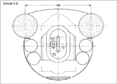
Cross section through the fuselage
at the spring for the final wing positions
This steel spring (AF) affects particularly to the mass of the wing via the
inner wing lever. The maximum spring force is about 1000 N. First, it decelerates
the incoming mass of the wing and accelerates it again in the opposite direction
in the area of the upper and lower stroke position.
The shown construction enables to use only one pressure spring for both final stroke positions of the wing. But under certain conditions one can dispense with a spring in the lower final stroke position (please take a look at the functional description of the drive of the ornithopter model EV8).
Without this spring for the final wing positions
the motor must spend
two times the torque for the acceleration of the wing mass at every wing beat.
But this is associated with related energy loss. It is more advantageous to
enable the oscillation of the wing mass with the aid of a spring.
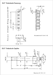
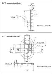
3.2 Detail drawings of the pin rack drive
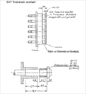
Pin-rack mounted
It is a rack bar with 6 steel pins assembled with rolls (of a roller chain
with a pitch of 6 mm).
4. Related Links
- To operate the Rack and pinion drive system
The Wayback Machine, Internet Archive, 2019
https://web.archive.org/web/20190725161140/http://www.ornithopter.de/english/rack.htm (please wait a moment)

