Articulated flapping wings
Description of flapping wing constructions
which have been developed together with the EV-models
Content:
- 1. Requirements of the flapping wing
- 2. Aeroelastic controlled articulated flapping wing
- 3. With adjustable twisting moment
- 4. With increasing wing twisting near the wing tip
- 5. Aeroelastic controlled
articulated flapping wing
with adjustable twisting moment and
expanding wing twisting near the wing tip - 6. Covering of flapping wings
- 7. Wrist for a strong passive
bending of the
hand wing with support of the lift shifting - 8. Related links
1. Requirements of the flapping wing
With large flapping wings it is too costly in terms of
labour to construct them according to the method of trial and error. It is much
better to limit the many error possibilities by calculations at least somewhat
(e.g. with the calculation tool Orni 1
).
The basics for the construction of a flapping wing are then, in addition to its
geometric data, the desired lift distributions during a flapping period. This
results in the forces occurring and the required torsion of the wing or the course
of the angles of incidence along the half span.
Here, for example, the relevant, extensively optimised functional distributions
for a gently inclined flight of a rectangular flapping wing with the all-round
airfoil CLARK-Y are shown (principles please see Handbook).
In this case, the angle of incidence at the wing root remains constant during
the whole flapping period. The distributions of the downwash angle along the span
are straight-lined in all three cases (please look at the diagram downwash
distributions
on the wing).
The weight of the flapping wing of course should be small. The same applies to the moments of inertia around the stroke axis of the flapping wing. This plays an important role during acceleration in the end positions.
There are recent findings about flying with relative constant lift resp. with wing turning during upstroke. If one is concerned with the construction of a flapping wing, one should also get to know the advantages and disadvantages of this way of flying. In particular, the long distance flight can be improved by the wing turning (please see Flapping wings with and without wing turning in German, PDF 0.7 MB).
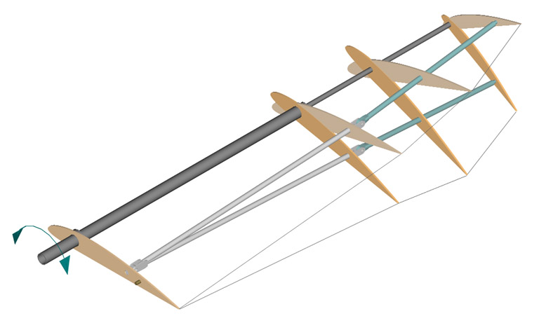
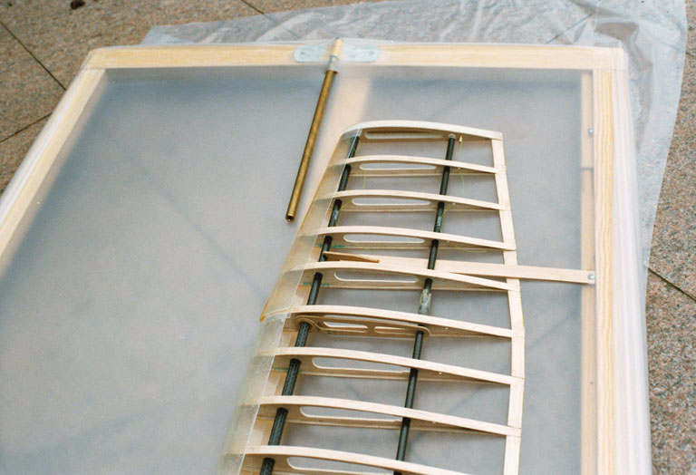
2. Aeroelastic controlled articulated flapping wing
Basic spar framework of a flapping wing for profiles
with known profile polares
with an articulation for an additional flap motion of the hand wing spar. This
is pulled down by a spring (spring device here not shown, please see Articulated
flapping wings, in German, PDF 1.3MB).
- While gliding flight with its medium lift force, the hand wing takes over the stretched centre position.
- On downstroke in the hand wing area the lift forces distinct increase and the hand wing strokes up against the spring force.
- If on upstroke the lift forces decrease the spring force pulls down the hand wing.
The small, on aerodynamic forces dependent and thereby aeroelastic stroke motion of the hand wing will be used by levers (brown for arm wing, green for hand wing) to control the twisting along the whole wing. In this way an articulated flapping wing with aeroelastic controlled twisting has been developed.
With the exception of the wing root rib all ribs are put freely turnable on the
spars. For the covering of the flapping wing the highly elastic polyurethane film
Platilon U 04
is planed (please look at related link 1).
The mode of operation of this articulated flapping wing, with its wing twisting
by wing bending against the stroke direction, resembles a little to that of a
bird's wing. In the case of the birds however, the turning or twisting movement
of the hand wing is mechanically coupled with its pivoting motion to the rear
(please take a look at the book ![]()
Anatomie und Flugbiologie der Vögel
by K. Herzog and the paper
Lift during wing upstroke, version 10.1, PDF 1.0 MB).
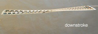
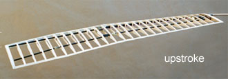
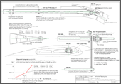
Technical drawing for a wrist joint of a flapping wing with slight bending
of the hand wing,
for the cruise flight
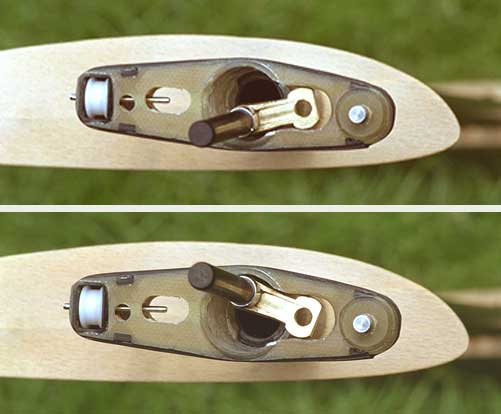
Wrist of the wing in up- and downstroke position
Wrist with the torsion lever of the arm wing and the wire rope to lock the wing twisting in gliding
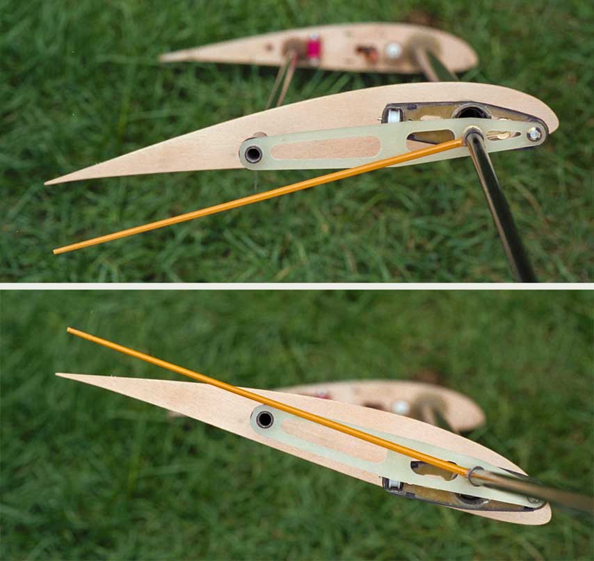
Function of the wrist.
of the wing
The yellow lever shows the turning of the hand wing.
The principle of this aeroelastic controlled articulated flapping wing I have developed in connection with the flapping wing model EV6 (1983). It has been continually improved and applied in the subsequent models.
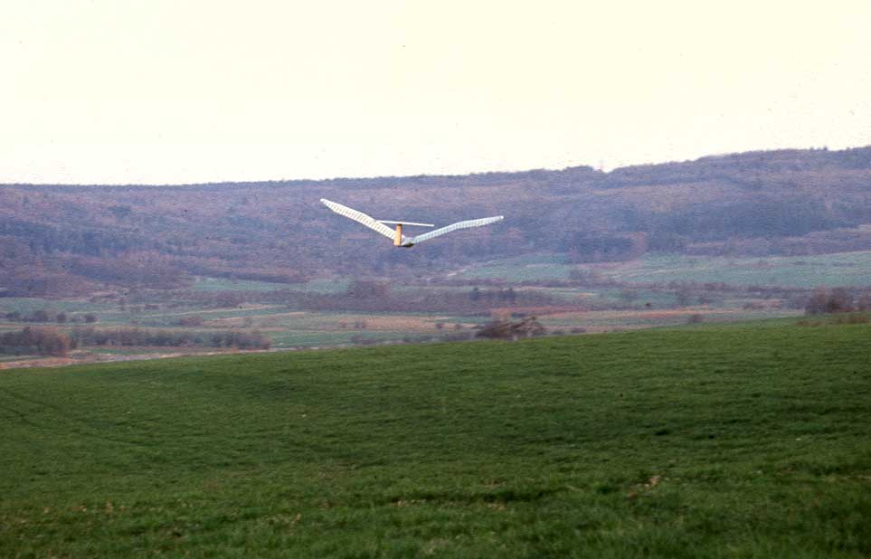
Ornithopter in flight, during wing upstroke
3. With adjustable twisting moment

By splitting the flapping and twisting tasks of a flapping wing on a main and an auxiliary spar its twisting moment can be designed adjustable.
Adjacent, the framework configuration of an aeroelastic twistable flapping wing with an adjustable twisting moment becomes obvious. The adjustment is affected by the torsion lever at the wing root.
The rest of the other ribs not shown here are fixed to the spars turning freely. The covering is done with an elastic foil or according to the Shearflex principle. Also shell and foam wings can be designed adjustable this way.
If you apply this system on a non-flapping aerofoil, a propeller blade or a wind turbine blade, their twisting can be controlled by the auxiliary spar.
Generally, the different types of wing systems can be combined together in many ways.
In the adjacent picture for example, the auxiliary spar of the arm wing with its torsional elastic force is used as a spring device for the small flap moving of the spar of the hand wing of an aeroelastic controlled articulated flapping wing.
The arm wing torsion linkage (AT) and the arm wing auxiliary spar (AHi) are hereby fixed firmly together. This way, the auxiliary spar-torsional moment will be transformed into a torque of the torsion linkage (AT). This is pivoted at the front and presses the hand wing spar down in the specified direction of rotation. The pressure will be adjusted with the inlying lever (InH) at the wing root.
The profiled arm part of this articulated flapping wing can also be combined with a membrane hand wing. This may be a flapping wing design for medial climbing and useful gliding flights.
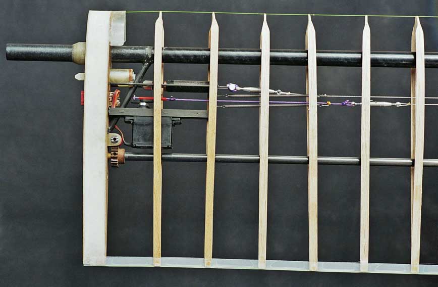
Adjacent, the wing mechanism near the fuselage with the setting mechanism of the turning moment of the auxiliary spar, the damper of the wing twisting at the upper final wing stroke position and the servo to keep the wing twisting in glide position.
4. With increasing wing twisting near the wing tip
This is the functional model of a
stroke amplitude expanding wing spar
in short form called shift spar
. This mechanism can be used at main
and at auxiliary spars of flapping wings.
If the shift spar is used as a rear auxiliary spar, it can be used to increase the wing twist in the range of the wing tip.
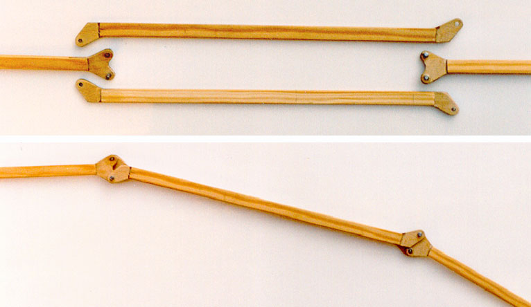
Image above:
Shift linkage dismounted
Image below:
Shift linkage mounted
The left hinge here provides as basis. At a stroke moving of the middle shift linkage - here downward - the outer right spar section implements expanded stroke amplitude.
Technical drawing
for a shift spar in a coaxial tube-in-tube construction
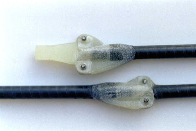
GRP joints of the shift spar
with different centre distances for transmitting the flapping motion (1:1.5).
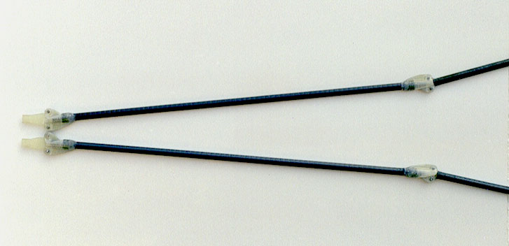
Complete coaxial shift spars
Adjacent one can see the spar framework of a profiled flapping wing for active wing twisting at the arm wing section by main spar turning.
There is a stroke amplitude expanding auxiliary wing
spar
is used. In doing so the twisting at the hand wing section is increased.
The spar shift linkage is hereby mounted coaxially.
The rib at the wrist is fixed firmly to the main spar and the auxiliary spar hinges fixed firmly to the wing root rib. All the other ribs are stuck on the spars turning freely. The covering is done with an elastic foil.
For a passive or aeroelastic twisting the rib at wrist should to be pivoted on the main spar.
5. Aeroelastic controlled articulated flapping wing
with adjustable twisting moment
and expanding wing twisting near the wing tip
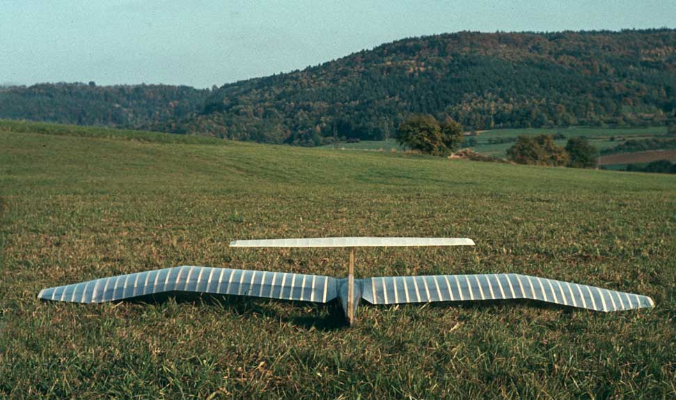
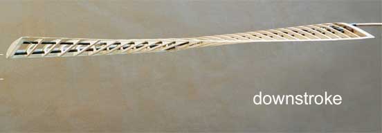
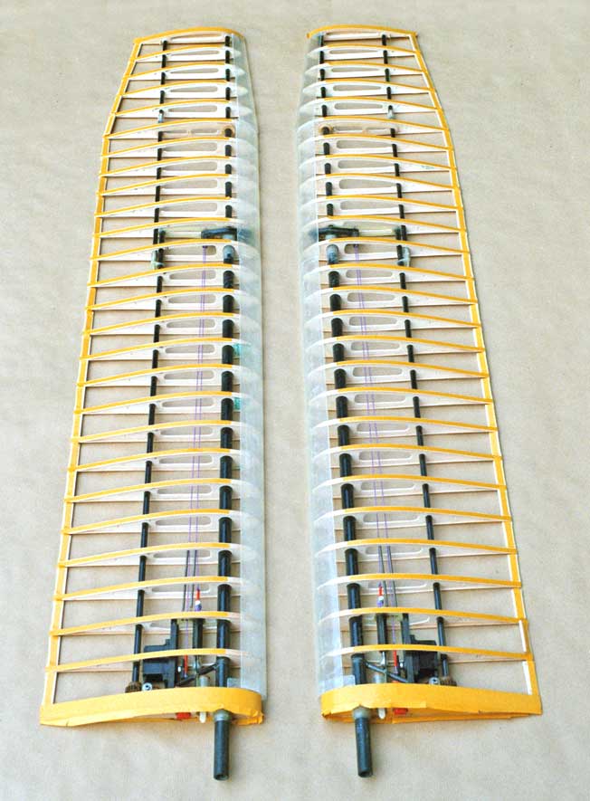
Wing framework of the model EV8
(2004), designed as an aeroelastic controlled articulated flapping wing, combined
with a stroke amplitude expanding auxiliary spar of the hand wing
at
the wing tip section. In order to achieve also a good glide, the wing was
designed without lift reserves, i.e. without increased wing depth.
- The twisting elasticity of this flapping wing can be adjusted by the torsion of the auxiliary spar of the arm wing at the wing root.
- The downstroke twisting is slowed down by a dashpot.
- The twisting when gliding can be fixed by a radio-controlled servo.

The downstroke twisting here corresponds with the theoretical guidelines almost to the wing tip (please also look at the picture which shows the wing structure in upstroke twisting position of the EV8). But still disturbing is the high mass moment of inertia of this flapping wing round its stroke axis of flapping and twisting.
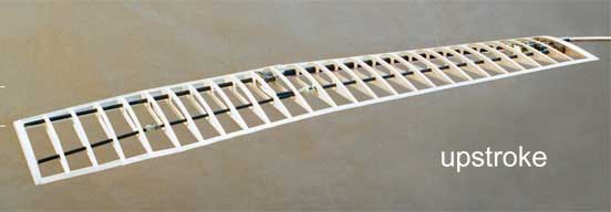
Maximum intended wing twisting (click on picture)
In flight practice the articulated flapping wing has a big advantage. The bending of the hand wing in comparison to the arm wing depends on lift of the hand wing. At the same time, it determines the distribution of the angle of incidence along the wing span. If the amplitude of the bending is estimable on flight pictures, the lift forces of the hand wing in comparison to the gliding flight can be estimated. Furthermore, the distribution of the angle of incidence in the moment of the picture was taken can easily be suggested (please look at EV6 and EV7). With these two information's selective adjustments of the twisting moment of the flapping wing, the driving power and the ratio of the cycle times are possible. Especially flight pictures taken approximately in the middle of up- and downstroke are informative.
Note
In this paper you can find some more details about the
Articulated flapping wings
(in German, PDF 1.3MB).
Information´s and suggestions for a further development you will also find in the article Lift during wing upstroke, version 10.1, (PDF 1.0 MB).
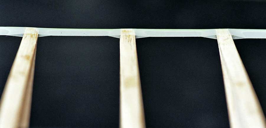
6. Covering of flapping wings
As well as for the other EV-models also for the EV8 a 0.050 mm thick elastic polyurethane-foil was used as cover for the aforesaid wing.
Double-sided adhesive tape was used adhere the foil to the wing framework (here still covered with release paper).
Version of a trailing edge for flapping wings, composed of a fishing line at the rear end of the airfoil which was wrapped with an adhesive tape. At the end of the balsa rib is inserted a tab made of k GRP with a hole. To make the tab, place a straight wire on a thin glass silk and fold glass silk around the wire After curing, pull out wire.
Here is the description of the manufacturing processes of the
Covering of a flapping wing with an elastic film
(in German, PDF 360 KB)
7. Wrist for a strong passive bending of the hand wing with support of the lift shifting
The downward bending of the hand wing during the upstroke in distance flight especially supports the
- reduction of the induced drag,
- avoidance of large negative angles of attack in the outer wing area,
- enlargement and equalization of the lift of a whole flapping period,
- concentration of the lift in the centre of the span and thus enhancement of the thrust, and the
- facilitation of the motion reversal of the wing in the stroke end positions.
Aerodynamically, the bending of the hand wing is particularly advantageous if the lift is high in the arm wing area during upstroke, e.g. due to a turning of the wing root.
7.1 Mode of operation of the bending
The single effects of a strong bending of the hand wing during upstroke in distance flight can be described as follows.
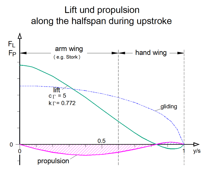
- During upstroke the oncoming flow to the wing comes more from above. If it is able to give way downwards by the passive bending, its lift will no longer be as negative as with the stretched wing (please see the diagram lift distributions in distance flight). This makes the overall lift larger and the profile selection easier.
- At a wing there is always a flow along the wing due to different pressures along the wing. It causes the vortices behind the wing and thus the induced drag (please see diagram induced drag on the site Handbook). This longitudinal flow is particularly strong when only the arm wing generates large positive lift. With its winglet effect, the bending decrease the longitudinal flow and thus reduces the induced drag. The longitudinal flow also becomes smaller because the lift in the hand wing area is no longer so strongly negative (please see point 1).
- From the large lift in the middle of the span, no more so much flows towards the wing tip. This helps with the concentration of lift in the middle of the span and thus with the generation of thrust.
- If the lift at the wrist is increased during the descent, e. g. as in the following image of the wrist, this also supports the concentration and enlargement of the lift in the centre of the span.
-
At the bended hand wing, a small oblique blow from above occurs. Thereby the lift is shifted a little bit along the hand wing in blowing direction, thus towards the wing tip. Birds strengthen this effect by pivoting the hand wing backwards (wing sweepback).
If there is positive lift at the wrist, negative lift is at least reduced by the oblique blowing, especially near the wing tip. This makes the profile selection easier. You can further enhancethe the effect by increasing the positive lift on the wrist during bending, e. g. as in the following image of the wrist.
In birds, the sweepback of the hand wing is coupled with a sweepback of the forearm. The associated oblique blowing of the forearm supports the concentration of lift at mid-span.
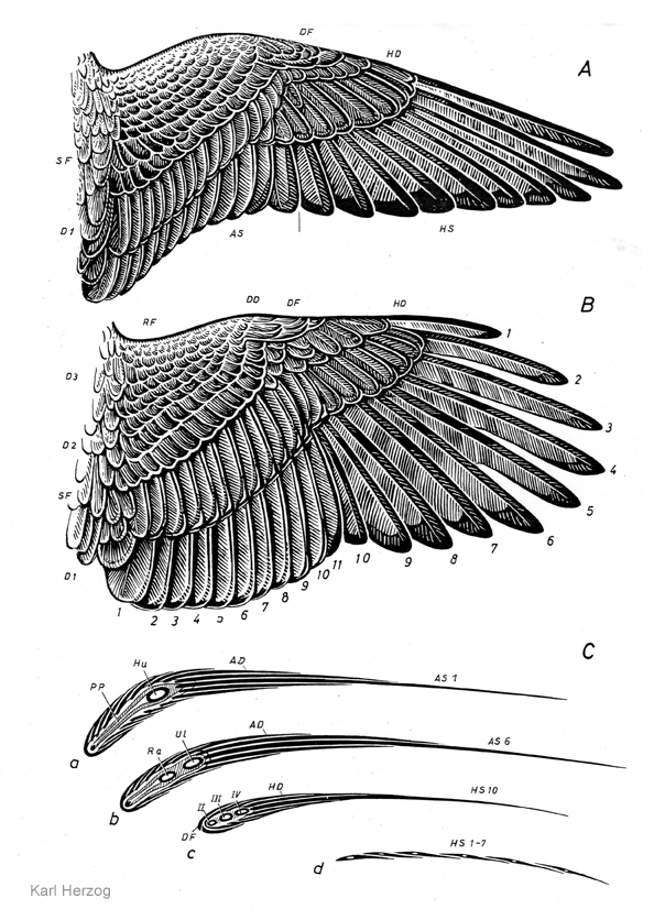
There is still a lot of experimentation to be done with the application of the oblique blowing. But the wing profiles in birds indicate, that there are rarely any negative angles of attack due to bending and pivoting of the hand wing (please see drawing of wing shapes and cross sections by Karl Herzhg).
-
The possibility to use the wind turbine energy of the arm wing for thrust generation in the outer wing area is strongly limited. The hand wing reduces its stroke path by bending and changes its direction of action. Furthermore, the negative lift is very small.
It must be checked whether the acceleration of the wing mass upwards, and there an end position spring, can absorb the whole wind turbine energy. Otherwise, a compensation spring is appropriate.
- With the bending, the sequence of wing twists in the individual wing sections can be coupled mechanically with the stroke motion near the stroke end positions. This supports the displacement of lift along the wing and thus the generation of thrust (please see chapter 7.3). In addition, it can be used to increase the lift during wing upstroke near the final stroke positions of the wing, thus without much working drag.
- The division of the flapping wing into two sections combined with the bending reduces the problems with mass inertia during the flapping motion in the area of the flapping end positions (please see Lift during wing upstroke, version 10.1, PDF 1.0 MB, chapter 7.3).
- The transition from the bent to the outstretched wing position begins, before
the arm wing reaches its upper final wing position. When the arm wing arrives
at the top, it should wait there, until the hand wing has reached the outstretched
wing position. Therefore, the drive should pause there for so long (please
see above paper
Lift during wing upstroke
, chapter 6.3, Fig. 20.)
The upstroke of the arm wing consists of a relatively fast upstroke motion, followed by a short waiting time in the upper stroke end position. - During take-off and landing with stretched wings a possible stroke movement of the wingtips must be considered.
- Even without a functional background, the bending during the flight of an ornithopter looks good. It increases the naturalness and liveliness of the stroke motion. It appears more harmonious.
- The calculations made here for lift, thrust, wing twisting etc. are no longer valid. One is again dependent on conjectures and on the method of trial and error, probably without measurements and comparison of intermediate results.
- With the bending of the hand wing described here, you can certainly achieve higher thrust values than without.
I only became aware now (2021) that the passive bending of the hand wing offers so many aerodynamic advantages. The engineering effort and the experimental requirements for the bending of the hand wing of an ornithopter are large. It has to be examined whether the various tasks can be solved in another way or can be done without it (e. g . by restricting to cruise flight).
7.2 Pivoting of the wrist axis
-
- Pivot angle κ (Kappa) of the wrist axis for an automatic increase of the angle of incidence of the hand wing by the bending
If one pivoted the wrist axis backwards to the inside
when bending, one
achieves an automatic increase of the angle of incidence when bending the hand
wing downwards (please see adjacent drawing). In this way, the angle of incidence
changes self-acting in the desired direction at the beginning and end of the upstroke.
This influence on the angle of incidence can approximately replace or at least
complement the twisting of the hand wing during upstroke.
During the bending of the hand wing, its angle of incidence or angle of attack increases. Due to increasing lift, the bending comes to a standstill already after a short upstroke motion of the arm wing. Depending on the upstroke speed, this is the case with a different bending. In this way, the maximum size of the bending automatically adapts to the beat frequency. The higher the beat frequency, the greater is the bending.
In birds, a corresponding, but only small change in the angle of attack of the hand wing is steered by the arm wing. When the stretched position of the arm wing is reached, the angle of attack of the whole hand wing becomes somewhat smaller and relatively inflexible (glide position). When the arm wing leaves its stretched position, the angle of attack of the whole hand wing becomes a little larger and more flexible again. K. Herzog 1968 has not written anything about a change in the angle of attack of the hand wing during the bending movement.
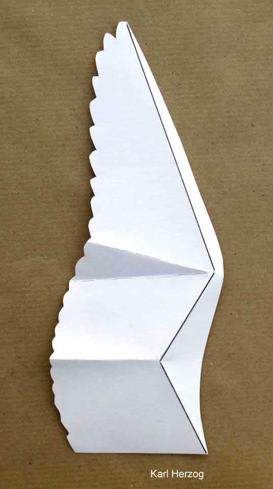
The paper bird wing by Karl Herzog shows a feather fan extending from the wrist to the back. When angled down, this fan obviously overlaps the different setting angles of the adjacent wing areas.
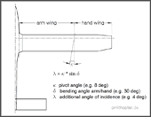
-
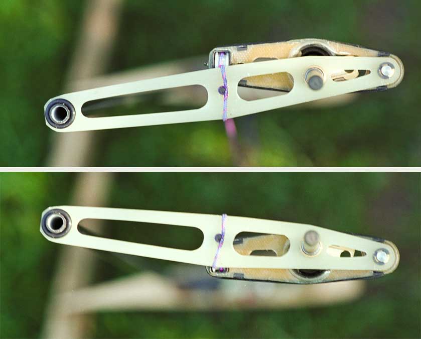
- Concept for a wrist joint of a flapping wing with strong bending of the hand
wing,
for the distance flight
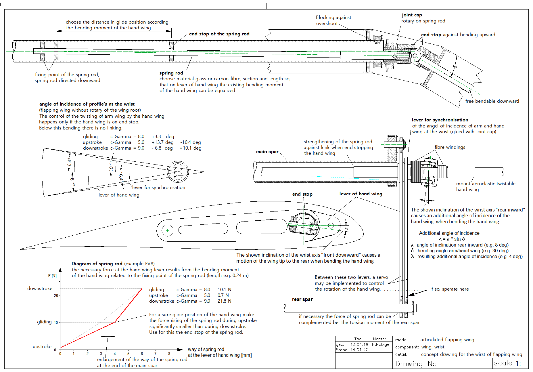
If one inclines the wrist axis front downward
(please see adjacent drawing),
the tip of the hand wing is slightly pivoted backwards when the hand wing will
be angled downward, although not so far as in birds (tip-reversal upstroke). Such
a small pivoting motion to the rear also only causes a correspondingly small increase
in the oblique blowing to the wing tip (for advantages of oblique blowing, please
see effects under point 5. above).
An example of an inclination and a pivoting angle of the wrist axis is shown in the concept drawing. The optimal size of these angles and their possible combinations must be determined by experiments. Unfortunately, there are no empirical values for this yet.
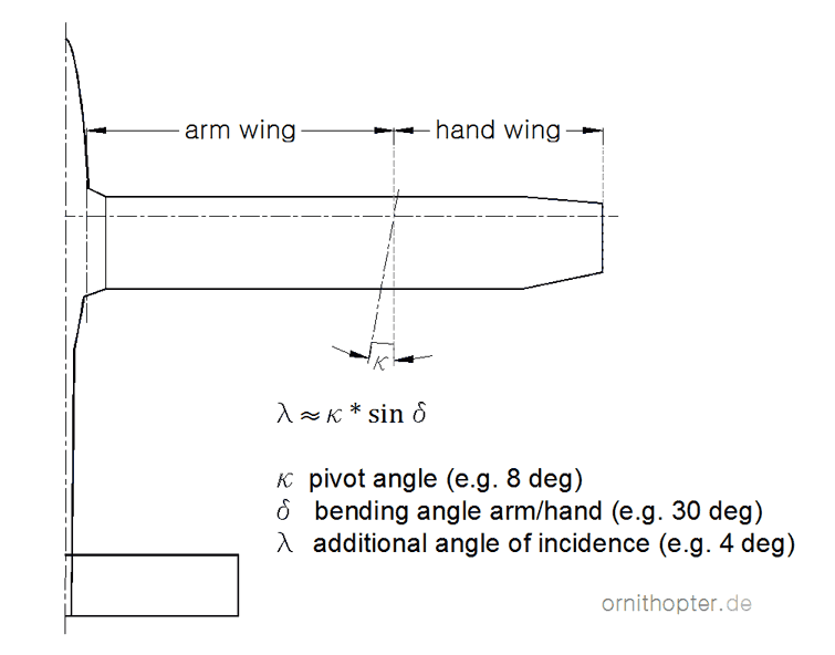
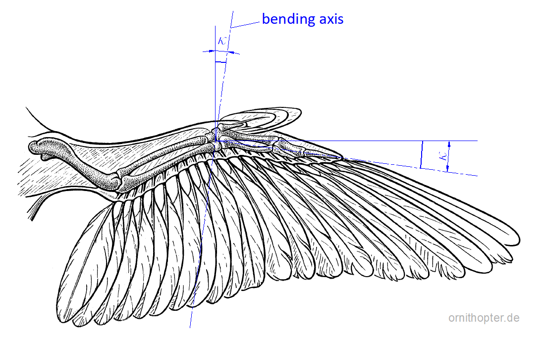
-
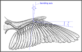
- Probable pivot angle of the bending axis from the hand wing on the slightly stretched bird wing.
When determining the pivot angle of the bending axis of the hand wing, one can
orientate on the pivot angle of bi birds with slightly stretched wings. When the
wing is slightly stretched, as shown in the adjacent picture, I assume that the
bones of the hand are approximately perpendicular to the bending axis. Because
there are barely existing muscles for twisting or turning of the hand wing (please
see Anatomy of a bird's wing and ![]() Karl Herzog, p. 46). However, the
alignment of the
Karl Herzog, p. 46). However, the
alignment of the axis
changes when stretching and pivoting the hand wing and possibly
also when bending strongly.
Due to the pivot angle, there occurs a small turning of the hand wing around its longitudinal axis when it is bent down. This makes the angle of attack large near the wrist. However, it still remains negative at the wingtip. This is exactly what is desired for the self-actuated bending. In addition, seen in the longitudinal direction of the wing, the large lift at the wrist supports the large lift at the arm wing. On the hand wing, therefore, its rotation is aerodynamically more advantageous than its twisting.
On upstroke with a barely recognizable bending, the elastic range at the beginning of the bending is already sufficient for changing the setting angle. There, the twisting of the hand wing is determined in particular by the widely together grown bones of the hand and by tendons.
With the articulated flapping wings used so far, it has
proven to be advantageous, also to control the twisting of the arm wing by the
passive bending of the hand wing. In the above wrist-concept
drawing, therefore, the fuselage near part of the wrist was approximately
taken over from the above aeroelastic controlled articulated
flapping wing (according to ![]() Karl Herzog, the wrist of birds is also divided
into two partial joints, a proximal ulnacarpal joint and a distal mediocarpal
joint). The necessary twisting of the arm wing during up and down stroke is thereby
already completely carried out during a small bending of the hand wing, in the
close range of the stretched wing position (please see click-picture
above and the Pictures of the flying EV7a).
If the hand wing bends further, the twisting of the arm wing remains unchanged.
This behaviour of the arm wing has advantages in displacement of lift.
Karl Herzog, the wrist of birds is also divided
into two partial joints, a proximal ulnacarpal joint and a distal mediocarpal
joint). The necessary twisting of the arm wing during up and down stroke is thereby
already completely carried out during a small bending of the hand wing, in the
close range of the stretched wing position (please see click-picture
above and the Pictures of the flying EV7a).
If the hand wing bends further, the twisting of the arm wing remains unchanged.
This behaviour of the arm wing has advantages in displacement of lift.
The motion of the spring rod should be blocked in the upper end position. Otherwise the moment of inertia of the hand wing will cause an overshoot of the angle of attack, like in the model EV7a.
7.3 Motion sequence of arm and hand wing
When the wing approaches the lower stroke end position at the end of the downstroke, the lift force in the outer wing section decreases. Also, the inertia of the hand wing now supports the downward movement of the spring rod. The spring rod increases the angle of attack of the arm wing, at least close to the wrist. In this way, the arm wing takes over the lift of the hand wing. In the lower final stroke position, thus there is a strong lift for a short time. But also, the angle of attack of the hand wing has increased during this time.
Also, with birds, not only the angle of attack of the arm wing, but with it also that of the hand wing is increased with turning of the wing root in the lower final stroke position. But only with a turning of the flapping wing the arm wing alone can absorb the whole lift for the upstroke. And only with a large lift of the arm wing are fully exploited the advantages of a wing bending downward. The large lift near the lower final stroke position supports the reversal of the flap motion of the whole wing.
The angle of incidence of the hand wing, which has increased in the lower end position,
becomes even larger in the course of its bending during upstroke. Due to the changing
direction of its oncoming flow, however, this does not apply to its angles of
attack. Along the hand wing will be occur a balance between positive lift close
to the wrist and negative lift in the area near the wing tip, until is reached
the maximum angle of its bending. This can then look in princiiple like in the
example of a stretched hand wing (pleas see the diagram
from the site Flight principle). Close to
the wrist, however, its angle of attack is still increased. Together with the
winglet effect of the hand wing, a larger lift can be held together
in
the arm wing and concentrated in the centre of the span, than without a strong
bending.
When the arm wing reaches the upper end position, its angle of incidence at the wrist initially remains large due to the spring rod. Thus, without upstroke motion increases its angle of attack. After the upstroke motion, possibly with wing turning to increase the lift in the middle of the span, so the lift is shifted a little to the outside. In the following waiting time, until the hand wing is stretched out, the arm wing has a very large lift near the wrist (compare with the animation of the swan). This is supported by the winglet or end plate effect of the still angled hand wing.
The large angle of attack at the wrist during the waiting period, naturally also applies to the hand wing. Its stroke torque upward is supported by the pressure equalisation of the adjacent large lift of the arm wing.
The advantage of the large lift in the upper stroke end position, is the missing wind turbine function with its negative thrust. Surely birds have such a possibility.
Subsequently also the hand wing reached the upper final stroke position respectively the extended wing position. There, because of the increased angle of attack at the wrist, grow its lift and thus its force upwards. As the spring rod now gives way, the angle of incidence on the wrist becomes smaller at the same time. Thereby the hand wing takes over parts of the lift from the arm wing. This continues because the angle of attack and so the lift of the hand wing increases further at the beginning of the downstroke.
The motion sequence of this wrist thus supports the process of lift shifting between the arm and the hand wings. In addition, the motion sequence of the two wing sections reduces the mechanical stress on the spar and the drive mechanism in the final stroke positions. The moment of inertia of the single wing sections is clearly smaller than that of the whole wing. But a good possibility to control the curve of the model or to influence the twisting or turning of the hand wing is still missing (Servo in the area of the hand wing).
8. Related Links
- Platilon U04
Thermoplastic Polyurethane Films:
https://solutions.covestro.com/de/marken/platilon
/ Downloads / Platilon U_en_20171205
or
http://shop.gesundheitsbett24.de/WebRoot/Store/Shops/es110028_shop24/Categories/NewShopServices/datenblatt_pu.pdf