The principle of flight of ornithopters
1. Definition
An Ornithopter, or ornitotero like Leonardo da Vinci termed them, is an aircraft
heavier than air, which flies like a bird by flapping its wings. The special feature
lies in the wings that do not only generate lift but also thrust. Ornithopters
are mostly built the size of birds or flying models and then are also called flapping
wing model
.
The basic operating principle of a flapping wing has already been discovered (1889)
by ![]() Otto Lilienthal . To help understanding
an effective way of flying of big ornithopters his functional description is still
trend-setting to the present day. Especially
Otto Lilienthal . To help understanding
an effective way of flying of big ornithopters his functional description is still
trend-setting to the present day. Especially ![]() Alexander Lippisch (papers 1925 - 1939)
and
Alexander Lippisch (papers 1925 - 1939)
and ![]() Erich von Holst (papers 1940 - 1943), as well
as the research work of many biologists have advanced the theory of the flapping
flight further. But many details are still not understood.
Erich von Holst (papers 1940 - 1943), as well
as the research work of many biologists have advanced the theory of the flapping
flight further. But many details are still not understood.
There have always been quite different variants of the flapping flight theory. They all exist in parallel and their specifications are widely distributed. Calculating the balance of forces even of a straight and merely slowly flapping wing remained difficult to the present day. In general, it is only possible in a strong simplified way. Furthermore, the known drive mechanism and especially wing designs leave a lot to be desired. In every respect ornithopters are still standing at the beginning of their development. But powerful drives make very beautiful flights already possible.
Also here follows only a variant of the flapping flight theory in short version.
2. Operating principle of the flapping wing
-

- Diagram 1
- Optimized lift distributions for a gently inclined climb flight with limited wingspan
-

- Diagram 2
- Optimized lift distributions for a gently inclined climb flight with unlimited wingspan


On a stretched flapping wing lift is generated similar to an inflexible airfoil which is flown from the front. But, during the wing upstroke the air flow hits the wing rather from above and in the downstroke rather from bottom. These modifications are small in the area of the wing root and gets bigger towards the wing tip.
With permanent changing twisting the flapping wing must adapt to these alternating incoming flow directions. However, the lift distribution along the span must not be kept constant, otherwise there is no thrust (please see adjacent diagrams).
During the wing downstroke the lift distribution is bigger altogether than when gliding and more displaced towards the wing tip. It is easy to imagine that thrust is generated along the whole wing span during stroke motion. This works similar to a propeller blade with a very large pitch - only that the propeller torque force that has to be overcome, is here called lift and is also used like that.
-

- Vector diagram of forces and velocities
-

- Forces at wing upstroke
by Otto Lilienthal


On the wing upstroke circumstances are reversed. Overall, the lift distribution is smaller and more shifted towards the wing root. With the stroke motion in the direction of the lift force the flapping wing now acts as a wind turbine blade. If the lift force is big enough it presses the wing upward even without a mechanical drive. Thereby, the wing operates with the operating drag or working drag of a wind turbine against the flight direction (please takes a look at the vector diagram).
At the same time, the outboard wing areas are flown against rather from above. There indeed is generated negative lift, but, similar to a propeller also thrust (please look at the vector diagram).
Whether in the upstroke the wind turbine or the propeller function dominates, depends on the wing twisting and on the shape of the lift distribution (for more details, please see following chapter).
-

- Comparison of aero-
dynamic machines

The adjacent picture clarifies, that the comparison does not apply in all respects to a propeller or to a wind turbine. The velocity proportions at the flapping wing are completely different. But the rotary machines are not designed for simultaneous lift generation. Furthermore, at the flapping wing the lift force at mid-span of the wing is never zero - as like at the rotary machines.
A flapping wing is an aerodynamic machine with two operating cycles, the upstroke and the downstroke. In unaccelerated level flight of a flying wing ornithopter the degree of efficiency of this machine is equal to zero. It only moves itself, but, emits no power.
But if you add a fuselage and a tail unit to the flying wing ornithopter the flapping
wing must apply power to overcome the parasitic drag. The flapping wing delivers
power. Now in seemingly absurd way, at otherwise same flight status, efficiency
is higher than before (bigger than zero). So, if the equilibrium of forces is
maintained, the efficiency increases with the size of the tail unit. So the parameter
efficiency factor
is relatively inapplicable for evaluating flapping wings
(please take a look at the Comparison of the
transport performance).
The flapping wing as an aerodynamic machine with two operating cycles constantly generates positive lift. In the direction of flight, however, it works with its thrust forward (downstroke) or backward (upstroke). Nevertheless, it is also possible at upstroke to use the entire drive energy for generation of thrust forward, with the three possibilities mentioned below. Of course, there are the usual losses due to the profile drag and the induced drag. However, this is always the case for the generation of lift. The advantage of the flapping wing working in the opposite direction during upstroke and downstroke, is the uniform generation of lift. In spite of changing directions of acceleration, flight velocity should be kept constant. Thereby are definitely advantageous a high flapping frequency and a large model mass.
The total thrust at the flapping wing gets bigger, the more the lift distributions
of upstroke and downstroke differ in size and/or in the distribution along the
span. This is especially true in the outer wing area, where most of the work is
done. If the difference equals zero, operating drag and thrust have the same size
and cancel out each other. The total thrust then is equal to zero (please look
at ![]() A. Lippisch 1938). If there is a difference
in lift, the thrust also increases with increasing flapping frequency and stroke
amplitude.
A. Lippisch 1938). If there is a difference
in lift, the thrust also increases with increasing flapping frequency and stroke
amplitude.
For a steady flight all forces - more precisely the force momentums (product from force and duration of action) - affecting the ornithopter during a complete wing stroke cycle must be in balance. The propeller effect must not only balance the wind turbine effect, but, also all remaining drags of the wing and the aircraft. At the same time, the positive part of the lift must outbalance the negative to an extent, that it can carry the weight of the aircraft.
2.1 Turning of the flapping wing
The course of the lift along the span is modified by the twisting of the flapping wing. But also, a turning of the wing at the wing root around its longitudinal axis changes the lift. The turning of the wing only influences the size of its lift in the calculation model, but not its distribution along the span (see adjacent figure). The wing twisting will be adjusted automatically. This would be different with the turning of a rigid wing.
-

- Changes of lift with a turning of the flapping wing during wing upstroke in the computer model

In the calculation model the turning of the wing root is indicated starting from the glide position. It is only indirectly determined by the selection of the lift size. For this purpose, the circulation factor kΓ is used (the circulation factor k-Gamma describes the size of the lift in relation to that of the gliding flight). In the adjacent figure the lift with turning of the wing root during upstroke by about +6 degrees, amounts to almost 80 % of the gliding flight.
The increase in lift by wing turning is limited by the maximum permissible lift coefficient of the airfoil at the wing root. By increasing airfoil camber and/or wing depth in this area, lift can be further increased.
Birds generally have a large camber of airfoil in the arm wing area and mostly a relatively large wing depth. The peregrine falcon (A) additionally needs a particularly large wing depth for the wing upstroke during stationary flight (please see examples for these wing designs).
In the generally used theory of bird flight the turning of the wing is not included. Also with the older lift distributions shown above the angle of incidence at the wing root is kept constant during the wing flapping motion (see above-mentioned diagram 1 und diagram 2). The peregrine falcon (A) additionally needs an even larger wing depth at the wing root, for the wing upstroke during stationary flight (please look at the diagram Downwash distributions from the site Handbook).
For the equalization of the total lift, E. v. Holst (1943) (p. 98, PDF 3.2 MB) already suggests a turning of the wing area close to the fuselage. The angle of attack near the wing root should be increased during upstroke and reduced during downstroke. He also realises this in his crank drive. According to the current state of knowledge, however, the turning should not take place during upstroke and downstroke, like in my flapping wing models EV1 to EV5, but, only during upstroke. A more recent suggestion is shown with the ball screw drive of the EV8.
Lift and propulsion along the wing
-

- downstroke
-

- upstroke


during downstroke
The propulsion is mainly generated by the hand wing, but, about 40 % also
by the arm wing.
during upstroke
When turning the wing root (here about +6 degrees) the negative thrust remains
relatively small, despite almost the same lift as in gliding flight (here approximately
80 %).
In large birds, sometimes the body or wing turning can be well observed. This is especially the case in flight situations with increased thrust requirements. This is always at the detriment of lift and can be compensated by wing turning. The turning is particularly strong near the lower stroke end position (see animations of a swan and a stork and the article Lift during wing upstroke, version 10.1, PDF 1.0 MB). The thereby resulting large lift generates so to speak, a large momentum of lift as reserve capacity. Then, the wing does not need to generate so much lift during the following fast upward motion. In this way the wind turbine function and the resulting negative thrust of the upstroke become smaller. Nevertheless, the sum of the momentum of lift will be large over the entire duration of the upstroke.
So, during upstroke one have the following possibilities to increase the lift in the arm wing, without the negative thrust becoming too great:
- In the close range of the lower final stroke position, i.e. during low stroke speed, starting already at the end of the downstroke, increase the angle of attack by turning the wing.
- In the same period as above, increase the angle of attack in the area of the elbow, e.g. by angling the upper arm (please see chapter 4.3 Anatomical shape changes of the arm wing),
- In the same period as above, together with the bending downward of the hand wing, increase the angle of attack of the arm wing near the wrist.
- During the fast upstroke motion, shift as much lift as possible to the span centre by twisting and turning the wing.
- In the upper final stroke position, maintain the large angle of attack of the arm wing in the area of the elbow until the arm wing is stretched (please see chapter 4.3 Anatomical shape changes of the arm wing).
- In the upper final stroke position, maintain the large angle of attack of the arm wing near the wrist, until the hand wing has finished its upstroke and the upstroke of the whole flapping wing ends.
For ornithopters, all this is difficult to achieve (example for 3. and 6. please see on site Articulated flapping wing, chapter 7.3 Motion sequence ... ).
If one uses the lift increases in the two final stroke positions, which are also possible without wing turning, the lift does not have to be very large during the fast upstroke motion. A turning of the wings with the aim of increasing the lift is not absolutely necessary. This may be a strategy to generate enough lift during upstroke even without wing turning.
Very thorough observations of the bird flight and interesting ideas of the wing upstroke and the wing turning also shows Brendan Body`s homepage, external link 1.
3. Flapping wing properties during flight
3.1 Gently inclined climb flight
At the wing upstroke the aerodynamic forces along the wing can be adjusted by suitable wing twisting so, that the turning moments round the wing hinge balanced themselves (please look at the following diagram 3). Here, the wing area close to the fuselage acting as a wind turbine directly powers the outboard wing area acting as a propeller. This is the 1st possibility to use the wind turbine energy.
There is no consumption or transfer of energy at this upstroke configuration. The wing can virtually be flapped up by the drive without effort. Propeller and wind turbine effects cancel out each other. The overall effect of the upstroke in the thrust direction is thus equal to zero.
-

- Diagram 3
- A special lift distribution at the upstroke, when the stroke torque of the inner and outer wing section balanced exactly each other. Thus, the wing can be moved upwards without an external force.

Due to the leverage of the wing at this upstroke setting the positive lift close
to the fuselage must be bigger than the negative lift near the wing tip. In total
there still remains some positive lift at upstroke (![]() Otto Lilienthal 1889). The wing downstroke
with its generally strong generation of lift and thrust can ensure the balance
of the remaining forces during the whole stroke cycle.
Otto Lilienthal 1889). The wing downstroke
with its generally strong generation of lift and thrust can ensure the balance
of the remaining forces during the whole stroke cycle.
As can be seen from the underlying lift distributions in diagram 1 above, the average lift of the two operating cycles are different in size. At least at low flapping frequency this will result in an obvious pendulous motion of the fuselage. But due to thereby generated variations of the angle of incidence it deadens itself quite effectively. These variations are not included in the diagrams.
Would one do without lift in favour of thrust generation in the upstroke, the following should be considered. To generate the complete momentum of lift only in the downstroke - so, about in half of the available time - the lift force and consequently the wing area, too, would have to be almost doubled. This and the corresponding lift fluctuations are only appropriate in exceptions.
The only way to reduce negative thrust despite strong lift generation during the
upstroke motion, is the concentration of lift in the mid-span (please see Distance
flight
in diagram Lift distributions
during wing upstroke from the site gait change).
One can support this by bending the hand wings downward (please see Mode
of operation of the bending.
To enable in birds strong lift during upstroke at inboard section of the wing, it is equipped with large airfoil camber. Only rarely is increased the wing depth at the wing root.
Of course, other settings are also possible in the close range of the lift distributions in diagram 1. They are well suited for gently inclined climb flights with a moderate flapping frequency. My EV-ornithopters have been built for this way of flying.
3.2 Mode of operation in cruise flight
IIn cruise flight the hand wing is stretched and there is positive lift almost along the whole wing (please see diagram lift distributions in distance and cruise flight from the site gait change). The wind turbine effect now present at the wing upstroke can now no longer be fully utilized in the outer wing area for thrust generation. The wing section with propeller effect is simply too small.
-

- Forces at the wing of a stork
during up- and downstroke
by
Otto Lilienthal

According to a proposal by Otto Lilienthal, the wind turbine or the wing upstroke energy may also be used again in a 2nd possibility. At first, the operating drag slows down the flying ornithopter. Thereby detracted kinetic energy of the model can be accumulated in a spring. This spring must be positioned in a fashion that it is tensioned at the upstroke. It removes the tension in the downstroke and supports thereby the flapping motion. The thereby generated thrust transfers the wing upstroke energy back to the kinetic energy of the model.
A 3rd possibility for using the wind turbine force lies in the acceleration of the wing mass in upstroke direction. If the wings are then slowed down at the upper final wing position by a spring and accelerated in downstroke direction, retransfer of the upstroke energy is also effected in this way.
In the upstroke a mechanical drive of the flapping wing is not necessary in these cases. The wing even releases energy to the above-mentioned springs. Anyway, the wind turbine motion must act against any force. Otherwise, no lift can be developed on a free movable wing. Therefore, it is necessary to guide the upstroke motion, e. g. by rotation speed control or limitation of the upstroke speed. The energy emitted during wing upstroke is normally relatively small. This is especially true when the lift is concentrated in the middle of the wing span.
Swan after take-off

- Close to the water surface a Mute Swan in distance flight.
- Slower and augmented (0.4 MB)

-
The downstroke twisting is negligibly low.
-
In order to generate sufficient lift during upstroke, the swan increases the angle of attack by turning the wing root. This already starts before the end of the downstroke. The turning reaches its maximum shortly after leaving the lower stroke end position and ends before reaching the upper stroke end position (for more details please look at Lift during wing upstroke, version 10.1, PDF 1.0 MB).
Such a variation in angle of attack near the wing root is a feature in the flight technique of many large bird species. However, it is not always so distinct as here, short after the start of this swan. But it will certainly also become a feature when starting large ornithopter models. -
During upstroke, the strong turning of wing decreases. This may give the wrong impression from the viewing direction, that the wing twisting changes the direction during the upstroke.
-
The leading inner wing section waits at the top until the outer wing section has arrived at the top.
-
In the upstroke the variation of the angle of incidence move like a wave from the wing root to wing tip.
The picture series has been presented to me by
A. Piskorsch privately.
-

- Diagram 4
- As a baseline, for gliding flight a lift distribution
is used here that is optimal for wings with unlimited span. The lift distribution
of upstroke is also optimal in relation to the induced drag.
(maybe used in gulls)
about like diagram 2

Altogether, in cruise flight the lift distributions of both of the operating
cycles have been approximated to this of gliding (please see adjacent diagram
and Cruise flight
in diagram Lift
distributions during wing upstroke from the site gait
change). It can get closer, the more streamlined the aircraft is built.
Because then is necessary less thrust. Furthermore, the induced drag of downstroke
decreases noticeably in this way.
Perhaps, it might be enough to shift the lift only a little along the span without changing its size. However, for that is nessessary a turning of the wing root.
Seagull in cruise flight

- Slower and augmented

An increase of the angle of attack near the wing root is not visible during upstroke.
From a 16 mm movie by
A. Piskorsch
When the cruise flight is perfected, according to ![]() Konrad Lorenz (1933) it shows in particular
the two following characteristics, a very slight, sometimes barely observable
bending of the hand wing downwards, and an approximately constant carry force.
Thereby an up and down swinging of the bird is no longer observable (for more
information please see the site Gait change, chapter 4.).
Konrad Lorenz (1933) it shows in particular
the two following characteristics, a very slight, sometimes barely observable
bending of the hand wing downwards, and an approximately constant carry force.
Thereby an up and down swinging of the bird is no longer observable (for more
information please see the site Gait change, chapter 4.).
3.3 Strong inclined climb and hovering flight
Similar to a helicopter during flapping flight the weight force can be balanced
by a thrust jet directed downward or by a thrust force directed upward. It is
the Flying with thrust
. Thereby, the wing upstroke practically
happens only with the drive. At least in steady flight, the thrust force is always
perpendicular to the stroke plane of the wing. Therefore, the thrust force can
be aligned with the inclination of the stroke plane of the wing.
-

- Small bird in approach

If the thrust force points exactly in direction of flight, there is either pure flying with thrust (perpendicular climb flight or hovering flight) or pure flying with lift (level flight). At settings between these extremes, the balancing of the weight force resulted by thrust as well as by lift. These mixed configurations are also assigned here to flying with thrust.
At least for large ornithopters, starting from a standing position, hovering on the spot, a strong inclined climb flight, or a very slow level flight, can only be realized by flying with thrust. Cruising flight or the distance flight, on the other hand, can only be achieved by flying with lift.
In flight praxis, especially the inclination of the stroke plane acts as identification criteria for ways of flying. In level flight it is nearly vertical to the flight direction. If it differs considerably (more than about 10 degrees) it is flying with thrust. In addition, when passive wing twisting is used, a large twist during upstroke is an indication of this flight type - at least at high Reynolds numbers. Also, a relatively high energy consumption in relation to the speed in level flight also indicates flying with thrust.
-
")
- A. Pénaud (1872)
")
Flying with thrust can be carried out in technical model making since the beginnings of aviation. At large and weightily ornithopters this way of flying demands considerably more energy than pure flying with lift.
In publications about the bird flight is rarely referred to the different flight techniques. The high-power consumption during slow flight is commonly only ascribed to the thereby increasing induced drag. But already Otto Lilienthal has distinguished clearly between two types of power flight in birds and has known the large amount of work in the slow flight.
4. How big birds fly
4.1 Flight with strongly fluctuating lift

- Supposed, approximate course of lift along the wingspan,
corresponding to the commonly used description of the flight of birds. -

- Size of lift forces on a flapping wing corresponding to the usual description of flapping flight, with strongly fluctuating lift.


In the commonly used theory of bird flight, a lot of lift and thus also a lot of thrust is generated in the outer wing area during downstroke. Thus, the outer wing area is guided upwards without significant power delivery. This is especially to avoid working drag during upstroke (please see adjacent diagrams and the description of the commonly used theory of bird's flight at external link 2). About a turning of the wing root or other measures to increase the lift in the arm wing area during the wing upstroke is nothing reported. The lift at the wing root is accordingly small.
This theory describes a distance flight with strong fluctuating lift and orresponding carry force. However, the up and down swinging of the bird's body is observed only rarely. It also occurs only during distance flight. The cruise flight is generally performed only with approximately constant lift (please see Gait change of birds, chapter 4.). The common theory makes no difference between these two types of flight, that is with or without bending of the hand wings.
With fluctuating lift, a vortex ring is created, especially during downstroke. This floats away to the rear on upstroke. Thus, in addition to the wing tip vortices a series of vortex rings formed along the flight path. The starting vortex generated at ring formation increases the induced drag and thus the required drive energy. Therefore, such vortex rings should be avoided by keeping the lift as constant as possible.
For ornithopters it is easier to realize the method with strong fluctuating lift, as described in the commonly used physics of bird's flight. There is then no need to turn the wing root or to take other measures to increase lift in the arm wing area during wing upstroke. But then you must relinquish about half of the possible lift capacity and compensate for this by flying at a higher speed. Thus, the carry force is low in this mode of flight. This is certainly one of the reasons why man-carrying ornithopters have not yet been able to get off the ground (please see also Lift during wing upstroke, version 10.1, PDF 0.9 MB).
When a seagull is flying with a strong headwind, its whole body swing up and down, something like at the gull in a gusty wind (animation, 0.5 MB). During its motion downward, in this way the inflow at the wing root is more from below. This creates thrust, please note thrust at the wing root. Besides, this increases the lift there. However, this was not yet investigated in closer detail.
4.2 Flying with approximately constant lift
-

- Basic principle of lift and thrust generation in birds flying with a large rate of advances (this especially occurs in large birds).

In the adjacent image E. v. Holst (1943) (PDF 3.2 MB) sketches how, in principle, an optimal thrust generation can occur in birds flying with a large rate of advance. His thought experiment will be slightly modified here. The shiftable wings shown here are not really to be moved, but merely to embody the shiftable position of the centre of lift.
-

- Shift of the center of lift (Lc) along the span of a flapping wing

At the upper reversal point of the stroke motion the lift centre is shifted towards the wing tip and at the bottom point to the wing root. Seen over a whole stroke period, while maintaining the lift L, the thrust T is greater on the downstroke than on the upstroke. The shift of lift is achieved by the aerodynamic interaction of the arm and the hand wing (e.g. the wing root is turned during upstroke). With this method, the Continuous-vortex gait will be realized.
-

- Thrust generation on a flapping wing when flying with approximately constant lift. The total thrust of a stroke period is positive.

With this ingenious trick of nature, it is possible to generate much lift also during the upstroke and nevertheless, seen over an entire operating cycle, a thrust generation is made possible. Since birds are very streamlined shaped, a relatively small shifting of lift is sufficient for them during cruise flight (see for example the position of the centres of pressure in diagram 4, above).
Stork in cruise flight

- Slower and augmented

In contrast to small birds, here the wing feathers are spread out during up- and downstroke.
The nodding motion of the bird's body causes an increase in the angle of attack on the wing root, especially at the beginning of the wing upstroke.
From a 16 mm movie by
A. Piskorsch
-

- Lift distributions, during upstroke with maximum possible lift in the arm wing area, on a rectangular wing with the profile CLARK-Y

Professor Jeremy Rayner has researched the flight of birds at the University of
Leeds (England). Thereby he also already largely described the way of flying with
constant circulation or constant lift (see article Vertebrate
flapping flight mechanics and aerodynamics and the Evolution of flight in bats
in ![]() Nachtigall W. 1986, BIONA-report 5).
He emphasizes the importance of this gait and sees its strong experimental confirmation
in the flow visualization experiments with a kestrel in fast flight by G. R. Spedding
(et.al., 1984, 1986, 1987). The resulting image of the Continuous-vortex
gait shows a non-planar vortex pair closely following the wings, with variable
mutual distance between the two wing tip vortices (please look at external
link 3). According to J. Rayner, the starting point of each tip vortex
at the trailing edge of the wing moves bidirectionally between the wrist and the
wing tip. Approach vortices are not visible.
Nachtigall W. 1986, BIONA-report 5).
He emphasizes the importance of this gait and sees its strong experimental confirmation
in the flow visualization experiments with a kestrel in fast flight by G. R. Spedding
(et.al., 1984, 1986, 1987). The resulting image of the Continuous-vortex
gait shows a non-planar vortex pair closely following the wings, with variable
mutual distance between the two wing tip vortices (please look at external
link 3). According to J. Rayner, the starting point of each tip vortex
at the trailing edge of the wing moves bidirectionally between the wrist and the
wing tip. Approach vortices are not visible.
-

- Size of the lift forces on a flapping wing in distance flight with approximately constant lift and during upstroke with bent hand wing

If the bird flies in distance flight with approximately constant lift, the lift force at upstroke and downstroke has in principle the magnitude ratios as in the adjacent diagram. The large lift at upstroke on the arm wing is achieved by its change in shape when it is angled. This is supported by a strong bending of the hand wing, possibly combined with a turning of the wing root. Sometimes the distance flight is also executed with strongly fluctuating lift. It then can be recognized by its oscillating trajectory. This is especially the case in slow flight and/or with high thrust requirements.
The large lift on upstroke is only possible, because of the birds strongly cambered high-lift profiles in the arm wing area (please see following chapter 4.3). Together with the large wing depth, much more lift can be produced there, than with the hand wing during downstroke. As a result of the bending, the hand wing can operate with very little lift, even though it is directly adjacent to the high lift of the arm wing. With its winglet effect, the bend reduces the outflow of lift from the mid-span in the direction of the wing tip.
-

- Size of the lift forces on a flapping wing in cruise flight with approximately constant lift and at upstroke with outstretched hand wing

In horizontal cruise flight, the positive thrust on downstroke is only sufficient to compensate the negative thrust on upstroke. No thrust remains for a climbing flight. The advantage of this way of flying is the high performance over long distances.
For the large lift in the arm wing area, the shape changes in the arm wing are probably sufficient in this case. A bending of the hand wing is barely recognizable.
If one compares in this context the calculated examples in the article Flapping wings with and without wing turning (in German, PDF 0.9 MB) it confirms that equable and uneven lift have preferences. This is also the case there, because the size of the lift during wing upstroke is determined in particular by the choice of lift distribution. The flight mode with strongly fluctuating lift offers advantages for climb flight (see example 1, with c_Γ1=0) and the flight mode with relatively constant lift for long-distance flights (see example 10, with c_Γ1=5 or 6). But here, too, the general rule applies, what is good for the lift is detrimental to the thrust and vice versa.
Forces in a flapping period
-

- Flapping flight
-

- Bird flight


Flapping flight
with strongly fluctuating lift, according to the usual description of the flapping
flight. In birds, however, the corresponding pendulum motion of the body is only
rarely observable.
From the shown resultant R
you can derive the carry
force and the thrust (not shown here). Pendulum movements of the body as a result
of lift fluctuations are neglected here.
Bird flight
with constant circulation, according to the Continuous-vortex
gait
This gait shows no vortex rings in the wake of the wing. As consequence, it operates with a constant size of the circulation and thus also with a constant lift. This was distributed mathematically to the arm and hand wings for the illustration, using suitable lift distributions (wrist at 0.6 of half span).
In this example, this results in a slightly variable carry force and relatively small thrust. In the stroke end positions, with elliptical lift distribution, the carry force is the largest. Drags and pendulum movements of the body were neglected. To fly with constant carry force it is certainly necessary to work with slightly fluctuating lift.
A further clarification of the different theories of bird's flight is possible, in particular by measurements on technical flapping wings in wind tunnel. Thereby the effects of various twistings and turnings on the lift distributions along the span should to be researched. Also, the behaviour of the wing tip vortices and the downward bending of the outer wing-section are interesting.
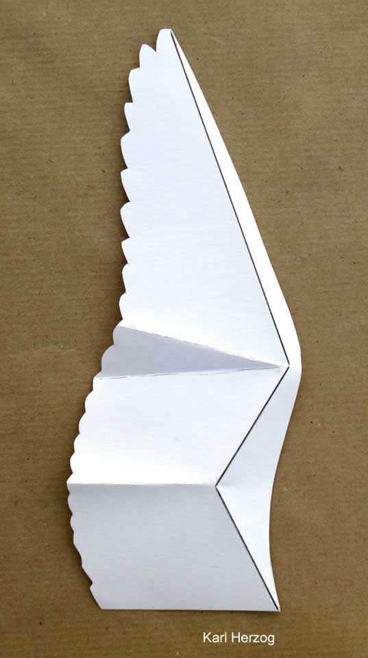
4.3 Anatomical shape changes of the arm wing
-

- Comparison of the wing depth of stretched and angled arm wing, or at wing
downstroke and upstroke, in a vulture (images
by
Heinrich Hertel)

In addition to turning of the wing, birds have other possibilities to change the size of the lift near the wing root. When angling the arm wing, for example, they can use the tendon of the forward flight skin (propatagium) to increase the wing depth, mainly in the part of the arm wing close to the body. Thereby they also increase the lift there (please see adjacent picture, especially the right wing-side). Birds also have these design possibilities during wing upstroke, whether with the hand wing extended or bent downward.
Also, because the forearm is mostly longer than the upper arm, the wrist is shifted forward when the arm wing is angled. This changes the direction of pull correspondingly along the tendon. In this way, the wing depth increases, especially near the elbow, and thus the lift along the whole arm wing. This shifts the lift of the whole wing more towards the mid-span. All this is also the case with the wing upstroke.
However, birds can also configure the arm wing in a different way. This can be
recognized on the left wing of the blue bird. There, the wing depth is kept almost
constant along the whole arm wing. The arm wing is more stretched. The way of
flying of the blue bird is described by ![]() Heinrich Hertel as
Heinrich Hertel as flat gliding
. Obviously,
this is a curved flight to the right. The black vulture soaring in the thermal,
on the other hand, curves to the left with inversely changes of both arm wings.
Unlike in technical gliding, here changes also take place on the inner part of the wing during the curving flight. On the inside of the curve, the incoming flow velocity is lower than on the outside. This is compensated by increasing the wing depth on the arm wing. In terms of induced drag, this is certainly better for stabilizing the curving flight, than corresponding changes to the outboard ailerons.
-

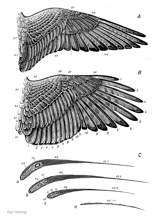
- Anatomy of a bird wing,
musculature top view
(by
Karl Herzog, 19688)

In the adjacent picture, each of the tendons (11a and 12a) of the fore and aft flight skins is held at the wing root by a small pair of muscles (11 and 12). They can vary the direction and the pull tension of the tendons within narrow limits. Changes in the pull tension or direction of a flight skin tendon affects lift in the arm wing area. However, it is largely unknown how and in which flight situations these muscles are used together with the arm extensor (9) and the arm flexor (10). For example, also in the enlargement of the wing depth. In flight, when the wing is slightly stretched as shown in the adjacent picture, the tendon of the front flight skin is sagged backwards in the middle of the arm wing (please see wing of a pigeon ).
Birds, however, can stretch the arm wing a little further against the pull of the tendon of the forward flight skin. Supported by the resulting strong pull of the tendon on the thumb knob of the metacarpal bone, the hand wing pivots forward a little. The elbow approaches the leading edge of the wing and the outer primary feathers will be spread. In the case of the soaring vulture, there is hardly to be seen any deflection of the tendon to the rear.
For the tension of the rear flight skin tendon, there are mainly determining the pull directions and pull forces of all muscles pulling on the upper arm bone (humerus). In flight, when the wing should not be angled so strong, the tendon is always kept stretched tight. Stretching and angling of the arm wing than will be realized almost nearly solely with the forearm. To increase the wing depth at the elbow, the humerus is pulled back just a little, probably with the muscle of the tendon of the rear flight scin. Only when the arm wing should be angled extremely during upstroke, or when balancing, the humerus will be directed more to the rear.
It would be interesting to know how the height position of the elbow relative to the connecting line between the shoulder and wrist changes when it is angled. The height position can be mechanically coupled with the angling of the arm wing. The position of the elbow determines the upper corner point of the forward downward inclined elastic flight skin (please see 3D-shape of the bird wing by K. Herzog). If the elbow moves upward, for example, it also pulls the front tendon with the flight skin in this direction. This is especially the case when the pull tension of the tendon will be loosened. This increases the angle of attack.
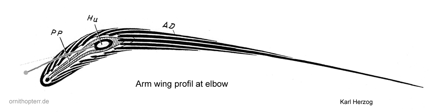
-

- Wing cross section at elbow of a hawk
wing
B
of the stretched arm wing in passive state.
The approximate position of the front flight tendon in distance flight at upstroke is indicated.
With its height position, also the size of the profile camber changes. The working range of the arm wing airfoil shifts accordingly. With a larger profile camber, larger lift coefficients are possible. And when the wing depth is increased by the front flight skin, the elbow shifts to the rear in relation to the airfoil depth. With it, the maximum of the airfoil camber also shifts.
The camber of the arm wing profile is elastic along the wing depth, particularly in the area of the front flight skin. This is also the area with the biggest pressure difference between the upper and lower side of the profile. The flight skin is thus aerodynamically pulled forward-upwards in flight. It is then curved upwards and pulls the fore tendon upwards with it.
The front tendon is bent even more forward in the middle during the upstroke than with stretched wing (please see image comparison of the wing depth). Thereby the e movement of the tendon upwards is facilitated there, and even supported by the pull forward. In addition, the wing depth is increased.
For anatomical reasons, the tendon will then probably be placed a little below the extension of the longitudinal axis from the oval of the displayed bone (please see the above image). This reduces the oversized camber of the profile that is displayed. At the same time, it increases the angle of attack. However, also the rear flight feathers bend slightly upwards in flight. This is aerodynamically advantageous for the wing upstroke. So, the flow does not stall on the underside of the profile. As a result of the angling of the arm wing during upstroke, the angle of attack in the area of the arm wing automatically becomes a little larger. With the help of the tension of the tendon respectively the angling of the forearm this effect can be varied.
-

- Vulture. Variable wing plan: Sailing-Gliding
(by
Heinrich Hertel)

The adjacent image is to illustrate in particular the possible change in size of the wing area. This is associated with a change in the flight speed.
However, the image also shows that when the arm wing is increasingly angled, the pull direction of the tendon of the front flight skin points very strongly forward in the area of the elbow.
Due to the strong sweep of the forearm, the lift there is shifted in the direction of the elbow as a result of the oblique blowing. This promotes the concentration of lift in the centre of the span during upstroke.
A similar, roughly approximated change in angle of attack on the arm wing can also be achieved on a technical articulated flapping wing. A change in the angle of attack on the arm wing can also be achieved without rotating the wing root. To do this, part the rear spar of the arm wing approximately in the middle. Both parts of the tie bar must then be reconnected with a joint. If you now control the angle of attack of the wing rib there, the angle of attack of the whole arm wing changes from there , strong in the middle and weakening at the ends. This helps in the aerodynamic interaction of the arm and hand wing when the lift in the hand wing becomes smaller at upstroke.
5. Related Links
- Tips and observations of bird flight by Brendan Body. On the subject of
Lift during wing upstroke
please see in particular the pictures and the video in chapter 8..
http://www.brendanbody.co.uk/flight_tutorial/index.html - Nathan Chronister explains very concrete the theory of the flight of birds
which is commonly used by biologists.
https://www.ornithopter.org/birdflight/flap.shtml - Tyson L. Hedrick, Bret W. Tobalske and Andrew A. Biewener,
Estimates of circulation and gait change based on a three-dimensional kinematic analysis of flight in cockatiels (Nymphicus hollandicus) and ringed turtle-doves (Streptopelia risoria)
(2002), Fig. 1.
https://jeb.biologists.org/content/205/10/1389