Ornithopter models EV1 to EV3
1. Ornithopter model EV1
- first flight
- wing span
- weight
- wing area
- wing loading
- max wing chord
- stroke cycle
- flapping angle
- 1975
- 2.90 m
- 5.4 kg
- 1,02 sq m
- 5.3 kg/sq m
- 0.44 m
- 0.8 s
- 60 deg
- [114 in]
- [190 oz]
- [1579 sq in]
- [17.4 oz/sq ft]
- [17 in]
1.1 Flight photographs of the EV1
The first flying electric bird
(Electro Vogel No. 1)
The inner arm wing was actively pitched and twisted. The outer hand wing additionally should also be aeroelastic twisted.
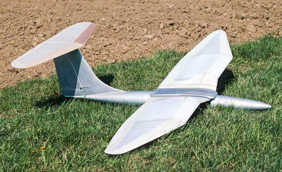
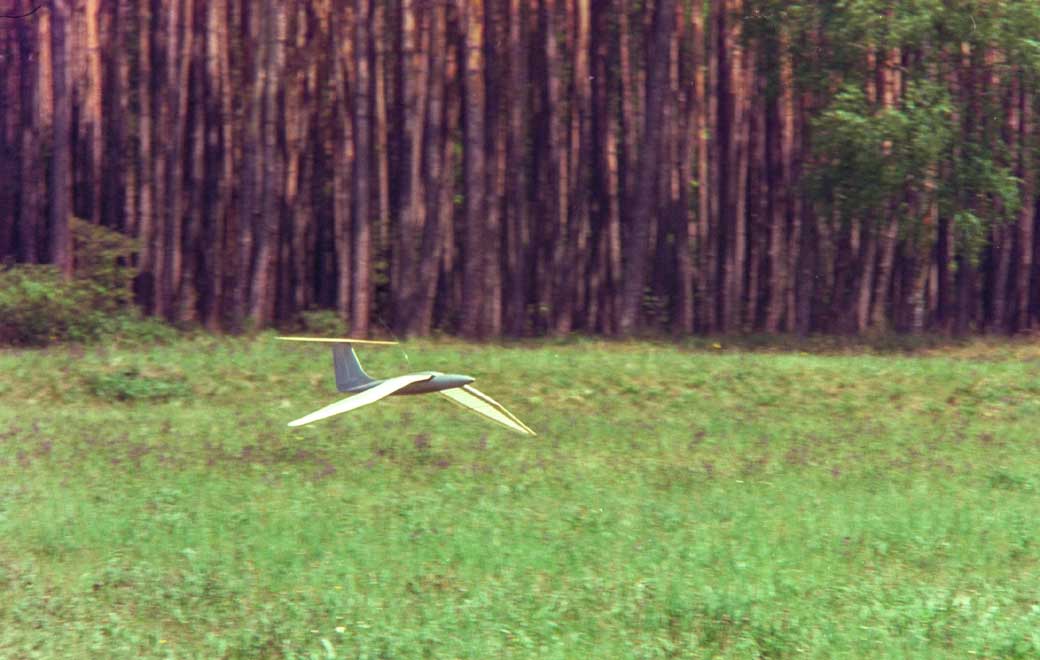
EV1 in powered flight

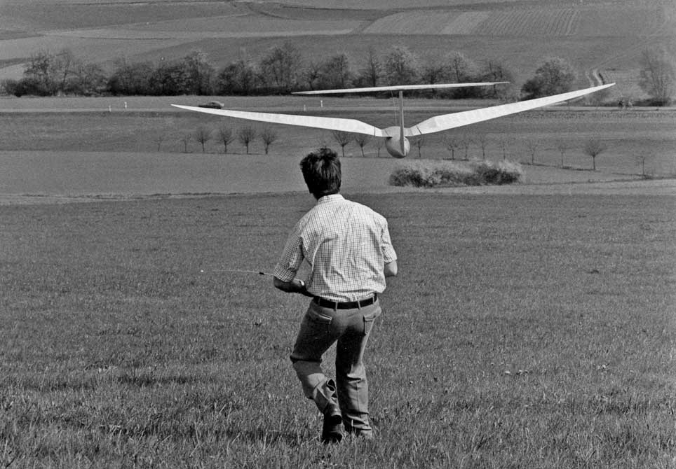
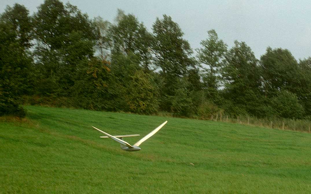
EV1 in gliding flight
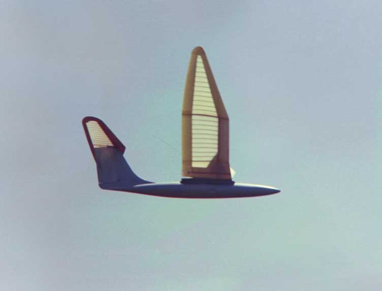
Wings in the upper final stroke position
The twisting along the whole span unfortunately was too small
for powered flight. It was made harder by the large rigid trailing
edge.
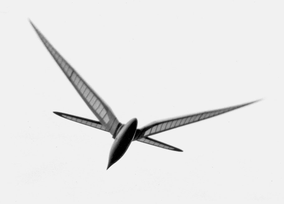
Wing twisting during the downstroke
Because the high wing loading the model flies relatively fast. The advantage
of this is that the wing twisting must not be big.
1.2 Manufacturing of the fuselage
Length 1.6 m, outer diameter 147 mm, fuselage side approx. 10 mm, made of rigid foam rings, covered with polyester-glass laminate.
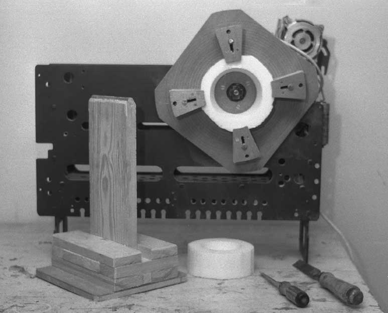
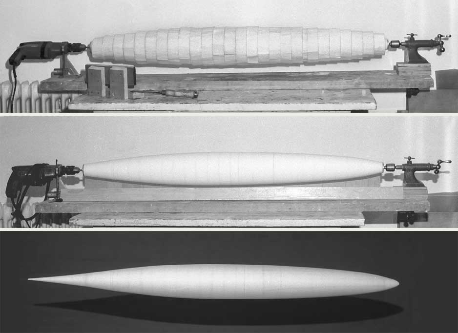
Making of the rigid foam rings
Making of the fuselage spindle
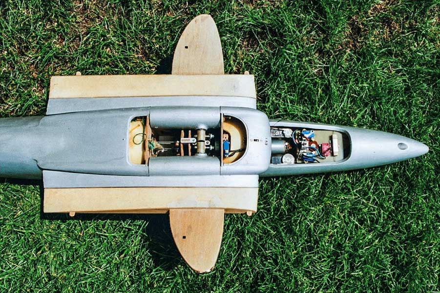
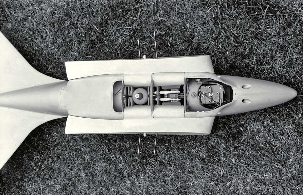
Open fuselage and wing attachment
EV1 was working with a wing root pitching.
Inside of each wing tongue
a mechanism was installed.
The wrist joints
in the center of the wing semi-span
were pitched with it additionally.
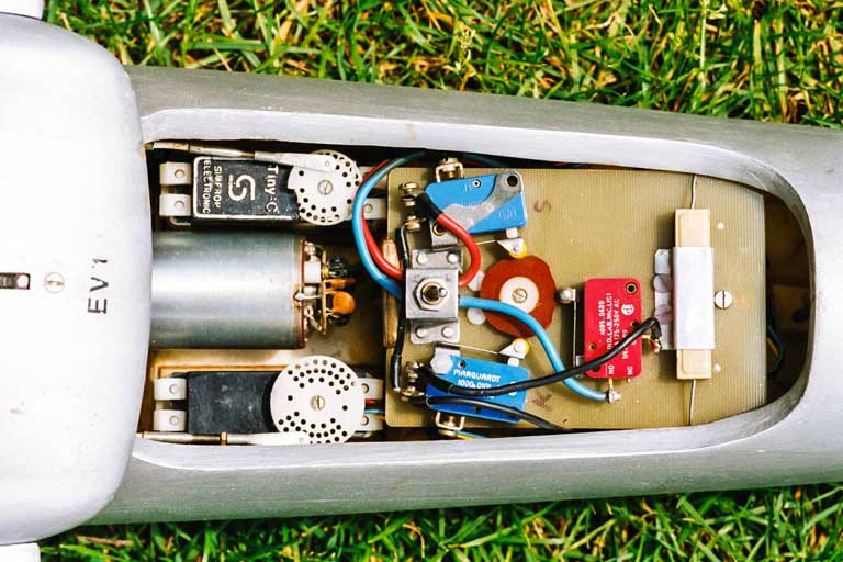
Electrical equipmen
in the front part of the fuselage On the left side you can see the drive motor and the servos for control the model.
On the right side the micro switches to reverse the motor and the
resistance for a smooth starting.
1.3 Drive mechanism of the EV1
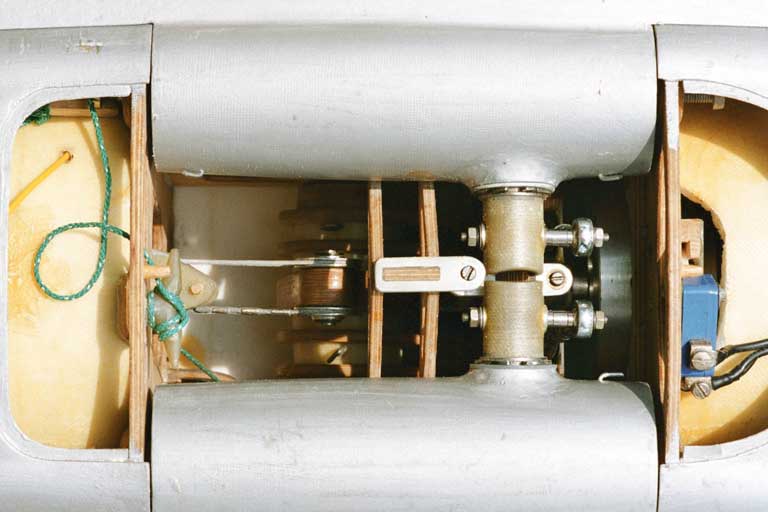
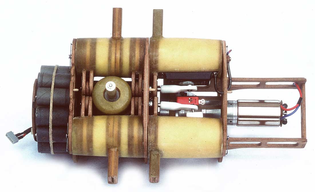
In the adjacent picture there are to see:
Left
One can see the fitting for fixing the cord of the pulley of the rubber compensating spring in the rear part of the fuselage (next picture).
Furthermore the steel wires between the pulley and the angled lever which presses the main scotch yoke up and the wings down, respectively.
Center
Support for the guide bar of the scotch yoke.
Right
Rods with spherical bearings to pitch the wing root.
Underneath one can see a bit of the drive unit and right of this the blue micro switch for the gliding position.
The spherical bearings of the main scotch yoke are pivoted inside the tube ends of the main spar.

By the drive mechanism with a cardan gear mechanism of the ornithopter EV1 the angle of attack of the flapping wing was adapted to the changing direction of flow while flapping motion by active turning of the wing root. This corresponded to the flapping wing theory by E. v. Holst. From today's perspective, the angle of attack on the wing root should be increased during the upstroke, but should not be reduced during the downstroke (see article Lift during wing upstroke, version 10.1, PDF 1,0 MB)
Inside of the wing the motion of the wing root compered to the fuselage could be used for an active twisting of the arm wing. Then, in additional the hand wing should be twisted aeroelastic.

Here you can see the pulley for tensioning the rubber spring. Their force action
lies in the order of the lift forces in gliding. Finally with 28 rubber
strips results a tension force of this compensating spring
of about
500 N.
Technical drawing
with a longitudinal section through the fuselage and the drive mechanism
of the ornithopter EV1.
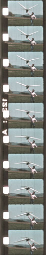
1.4 Video of the EV1 (1975)
From the EV-ornithopter models have been made only a few 8 mm films. Since we did not have a wide range of clips to choose from the quality in some cases is poor. Nevertheless you can get an impression of the style of flight of the models.
Testing of all driving functions was only possible with existing wing lift. Therefore, test runs were necessary at first. Particularly the switch between gliding and powered flight had been tested thereby.
1st flight:
The start of the first powered flight of an electrically driven flapping wing model is to be seen.
2nd flight:
The second flight, too only lasted a few wing beats.
Both flights looked somewhat miserable at first sight. However, relief was huge thereafter. There were no vertical movements of the fuselage. Furthermore, the novel cardan gear mechanism worked very well. Its switch between powered and gliding flight worked flawlessly. Further short flights could be executed.
| Download |
640 x 480 mp4 (1.9 MB) |
480 x 360 mp4 (1.0MB) |
320 x 240 mp4 (0.5MB) |
2. Ornithopter model EV2


- first flight
- wing span
- weight
- wing area
- wing loading
- wing root chord
- 1976
- 2.96 m
- 5.4 kg
- 0.92 sq m
- 5.9 kg/sq m
- 0.42 m
- [117 in]
- [190 oz]
- [1419 sq in]
- [19.3 oz/sq ft]
- [17 in]
The active twisting of the wings resulted from the separate controlling of the
main and auxiliary spars in stroke direction. For covering the wing the elastic
foil type Platilon U 04
was used for the first time, thickness 0.03 and
0.05 mm (for data sheet please look at the Related
Links of the Articulated flapping wings
).
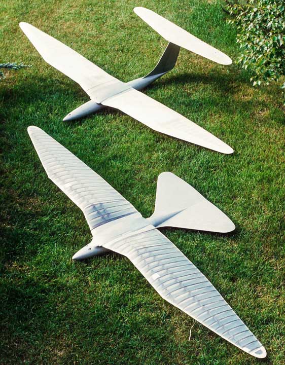
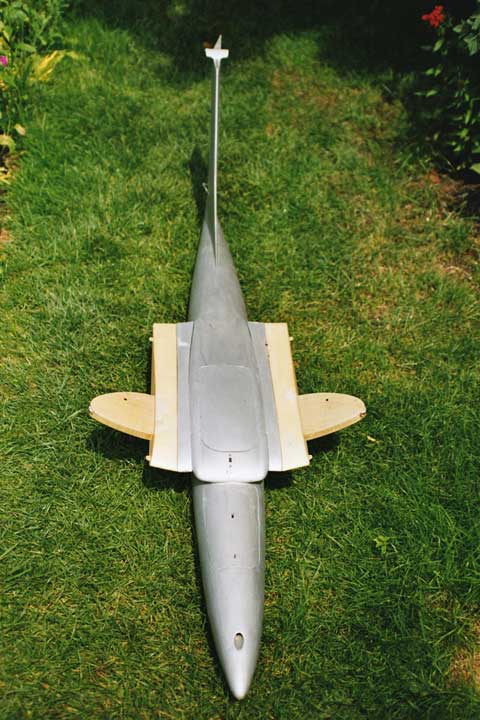
EV1 in comparison with EV2, top view
The main and the auxiliary spars were separately controlled by two steel wing levers (please take a look at Twisting by stroke movement of the auxiliary spar). In front one can see the micro switches to reverse between gliding and powered flight.

Like at the EV1 the blank of the fuselage was made of Rohacell rings covered with a glass fibre-reinforced layer. The rear part of the fuselage was detachable to change the batteries.
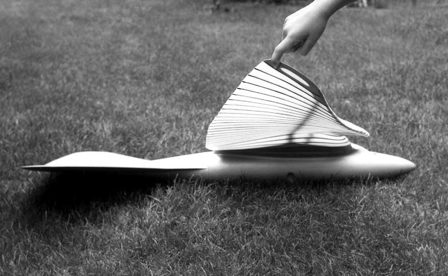
Wing twisting
2.1 Drive mechanism of the EV2
To the rear one can see the accumulators and the cover of the steel spring used for lift force compensation.
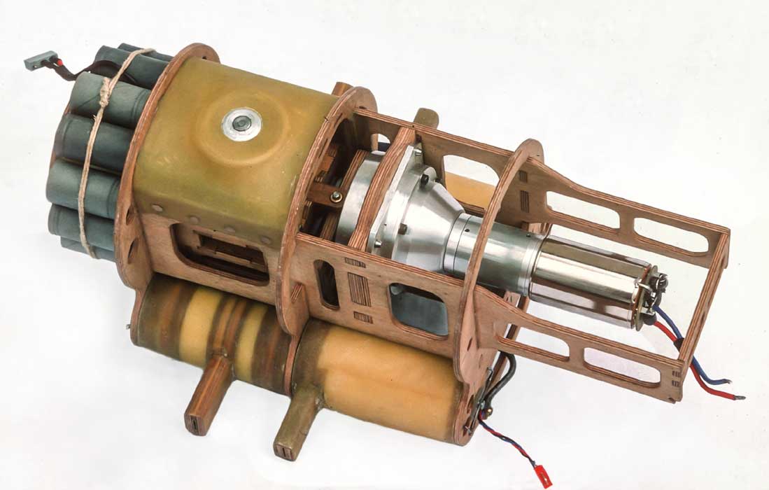
View from below to the drive mechanism
It was used the cardan crank with transition between gliding and powered flight
by reversion of rotation like in the EV1.
The servos to modify the wing twisting are inside of the front wing adapter rollers.
single components of the mechanism
Data of the steel spring: d = 4 mm, Dm = 40 mm,
k = 3.26 N/mm, Fmax = 536 N,
W = 184 g [6.5 oz]
Drawing (longitudinal section) of the drive mechanism
On the EV2 the flapping wings offers a good potential for a strong twisting. However, there was no capable flight result. Bearing clearances and undesirable elasticity of the wing spars plays a too big role. The adjusting, keeping and reproducing of a definite angle of attack was almost impossible in the area of the wing tips.
According to current experience and knowledge the used principle of Twisting
by stroke movement of the auxiliary spar
is inapplicably for ornithopters
with a large wing span. For the rest good substantial progresses at the
construction have been achieved with the EV2
(see report in chapter 4).
3. Ornithopter model EV3
No pictures
The EV3 did not get past the phase of design. Only plans exist (terminated 1978).