Other flapping wing designs
In designing of ornithopter models there are mainly two major tasks, the development of the drive technology and the development of the flapping wing. In general, the wide interest lies in the drive systems and components. But the main problem of the development of such aircrafts are the flapping-wings. In this field of design desire differs very widely from reality.
Below, the attempt is being made, to give a rough overview about the physical characteristics of known flapping wings. But this collection doesn't claim to be complete.
Content:
- 1. The bird wing, the ideal
- 2. Membrane flapping wings
- 2.1 The sail as archetype
- 2.2 Simple membrane flapping wings
- 2.3 Simple membrane flapping wing
with battens - 2.4 Active twisting by spar turning
- 2.5 Aeroelastic twisting by spar torsion
- 2.6 Flying wing ornithopter
- 2.7 In tandem
- 2.8 Thrust-Wing
- 2.9 Oscillating stretched wing
- 2.10 Rotating wings
- 2.11 With non-twistable arm wing section
- 3, Profiled flapping wings
- 3.1 With artificial feathers
- 3.2 With inclined hinge of the hand wing
- 3.3 Twisting by tilting the leading edge
of the wing - 3.4 With stepped twisting
- 3.5 Twisting by stroke movement of the
auxiliary spar - 3.6 Servo controlled wing twisting
- 3.7 Shearflex principle
- 3.8 Oscillating wing tips
- 3.9 Shell wing
- 4. Notes
- 5. Related Links to other flapping wing designs
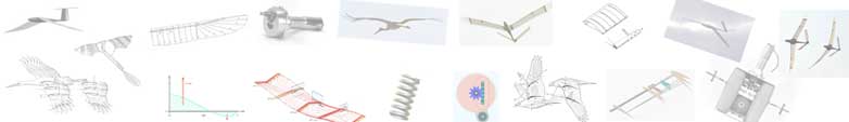
1. The bird wing, the ideal
Naturally, the great archetype for technical flapping wings is the living bird wing. His great effectiveness due to his manifold possibilities to move purposeful and to change the shape will certainly be unobtainable in aero modelling for a long time. This is also true for his weight distribution and his sensor technology.
In this drawing by K. Herzog the anatomic subdivision of the bird's wing in arm- and hand section is pictured. It can also to be used advantageously when describing technical flapping wings. The longitudinal parts of these wing sections are rather different depending on bird species.
2. Membrane flapping wings
Application range
Membrane flapping wings especially are changing the direction of chamber in the hand wing section according to the flapping direction. This way, they can produce much thrust and achieve steep climbing flights (flying with Thrust). But up to now they are less suited for gliding flights and for flying with lift.
2.1 The sail as archetype
A sail - though in other circumstances - has about the same function as a flapping wing. It shall generate as much thrust as possible under changing approach flow directions.
By material selection, layout, division into parts, sail trim and rig tuning the sail characteristics can vary in wide ranges. Battens give the sail more stability and an optimal shape. A lot of descriptions with sophisticated tips about the fabrication of the sail and its practical use can be found.
Indeed, a lot of systems of membrane flapping wings have been developed, but detailed information about them is barely available
2.2 Simple membrane flapping wings
The pinion feather
by
![]() Alexander Lippisch
(ca. 1937) obviously was optimized for thrust generation. Therefore, he increased
the chord in the outer wing area. But this pinion feather was not intended
for generating lift at the same time. It is merely a propeller for changing the direction of rotation.
Alexander Lippisch
(ca. 1937) obviously was optimized for thrust generation. Therefore, he increased
the chord in the outer wing area. But this pinion feather was not intended
for generating lift at the same time. It is merely a propeller for changing the direction of rotation.
Tim
was the first in
mass-produced rubber powered flapping wing model - with
simple membrane flapping wings - invented by Albertini
Prosper and de Ruymbeke Gérard (France 1969).

The membrane printing of Tim in the marginal picture was drafted by
K. Herzog.
Under the designation Tim Bird
this model is
available in trade till today.
2.3 Simple membrane flapping wing with battens
Here a famous Membrane Flapping Wing, equipped with small battens
for stabilisation of the membrane, developed by A. Pénaud
(France 1872).
more information at related link 1
2.4 Active twisting by spar turning
This is a membrane flapping wing by Erich v. Holst / Karl Herzog (1963) with drive-controlled wing twisting in the arm wing section by spar turning. Only the rib at the end of the arm wing (number 9) is fixed to the spar. It is linked with a crank drive which effects the stroke movement as well as the rotary movement of the spar.
The twisting in the hand wing section happens largely passively. In addition, a transition from cross to longitudinal battens can be seen. In spite of alternating profile chamber direction during a stroke cycle a relatively purposeful increase of wing twisting tip wards is made possible. The bird models by K. Herzog (1963) follow this scheme, too.
2.5 Aeroelastic twisting by spar torsion
The flapping wing model of the Czech Cenek Chalupsky (1934) was flying steadily without a tail unit. Its achieved climb power is still considered remarkable today.
- weight
- wing span
- cane spar
- covering
- ceiling
- 3.1 kg
- 2 m
- linen
- 10-15m
- [109 oz]
- [79 in]
- [394-590 in]
Each flapping wing of this ornithopter has two spars. The straight, bending resistant spar (H1) transmits the power of the stroke motion. The bended torsion elastic spar (h3) determines the magnitude of the wing twisting.
Both spars cross approximately in the center of the semi-span. At the cross point they are movably interlinked. For the torsion elastic spar (h3) not to pivote backward too much, a string or an elastic thread is apparently tightened between the tips of the spars.
During downstroke of the wings the lifting forces are increased. The spar h3 and the wing are twisting. The magnitude of the twisting acts in accordance with the magnitude of the lift force and the stiffness of the spar. It therefore happens aeroelastically.
Additionally to the twisting the tip of the spar h3 bends upwards in the downstroke. As a reaction it bends downwards at the other side of the
cross point - thus, in the section of the arm wing. Thereby, the camber
of the airfoil is increased a little. Thereby, an adaptation to the requirements
of an effective stroke motion takes place (please look at
![]() Piskorsch Adolf (1975),
Pressluft-Schwingenflugmodell Chalupsky)
and the vidio of the related link 2
Piskorsch Adolf (1975),
Pressluft-Schwingenflugmodell Chalupsky)
and the vidio of the related link 2
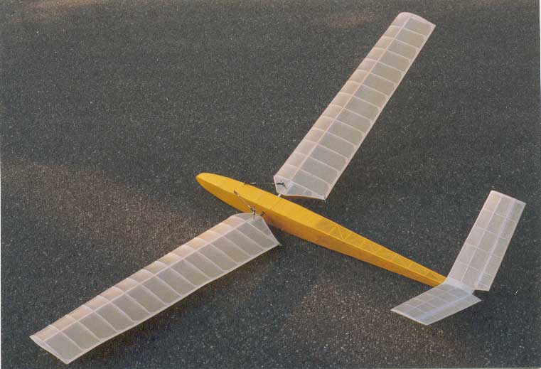
2.6 Flying wing ornithopter
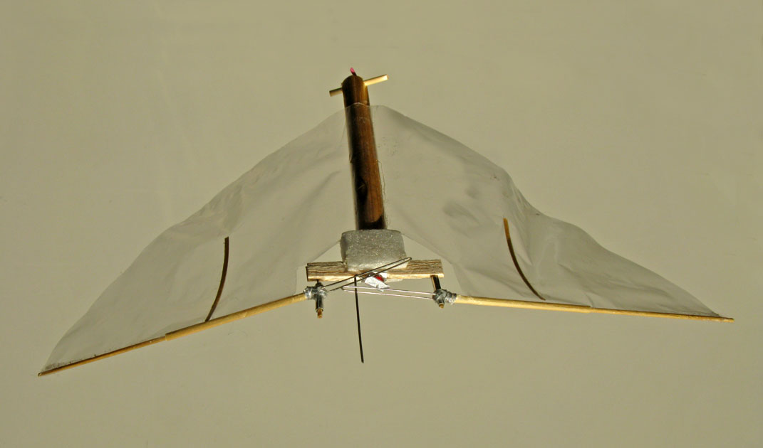
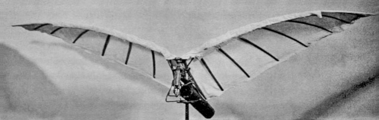
Here an ornithopter without a tail unit, developed by Jean-Louis Solignac (France, 2000).
The flapping wing model Kleiner Vogel
has a very simple and light driving mechanism
and is powered by a rubber motor. With a wing span of 15 cm (5.9 in) it
has a weight of only 0.6 grams (0.021 oz [US]). The airplane performances
are amazingly good (for the construction of the flapping
wing model please look at related link 3.)
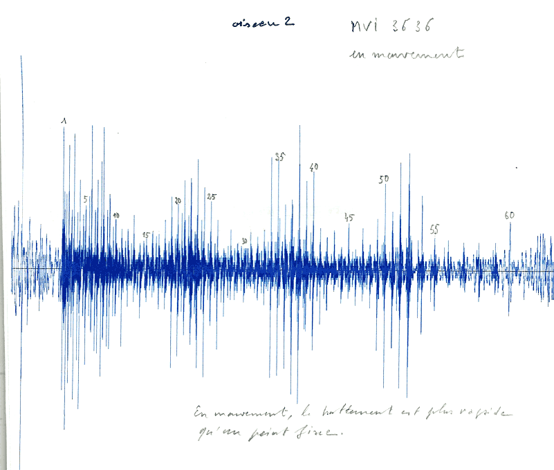
Acoustic recording of the flapping wing noises of Kleiner Vogel
.
This can be used to determine the flapping frequency.
The particular about this flapping wing is the down cambered airfoil shaped by battens. Thereby it flies in a stable attitude without a tail unit. This can theoretically be explained with the shifting of the center of pressure of thin airfoils. It can be tested in the adjacent experiment with a paper airplane. The cross-section of this paper airplane equates to a down chambered airfoil.

If you keep the center of gravity at the same
distance d
form the leading edge like at the paper airplane, also
a lightweight flying wing glider made of balsa is flying excellent.
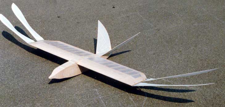
2.7 In tandem
Ornithopter with two sets of flapping wings based on a Dragonfly, developed by E. v. Holst (194o) / K.Herzog (1963).
Here, for simplifying the mechanism both opposite halves of a wing are rigidly fixed to a unit. Thus the center of pressure of the model is fixed between the two wing units.
In such tandem arrangements with wings flapping in opposite directions the vertical pendulousness of the fuselage should be avoided. This, however, bears the disadvantage that the backmost flapping wing is in the turbulence wake of the front one. Only for very small wings and at very small Reynolds numbers this may be beneficial. This is a model by Horst Händler (1988).
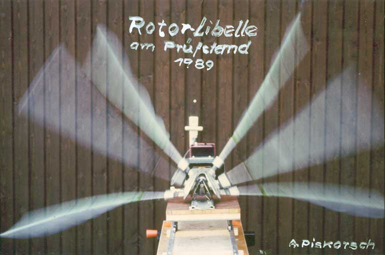
2.8 Thrust-Wing
By mechanisation of a Dragonfly's flight principle. ![]() Erich von Holst (1948) has developed his
Erich von Holst (1948) has developed his Thrust-Wing
with two in the opposite direction rotating three-blade wings (please
look at E. v. Holst with a video of the Thrust-Wing).

The flapping angle in one stroke direction constitutes 180° or 360° for a complete stroke cycle. Three instead of two wing blades per rotor offer a constant supporting force.
In contrast to a propeller at the Trust-Wing also can be generated a considerable lift force perpendicular to the direction of flight. One must only increase the rate of advance of the Thrust-Wing - similar to a normal flapping wing - and fly with a small positive angle of attack of the Thrust-Wing axis (The rate of advance is the ratio of airspeed to circumferential velocity at the wing tip.).
This is a fine example for an innovative transfer of biological principles
of a flapping wing in engineering. But the specialism bionics
did
not exist at that time.
The Thrust-Wing model ENTOID
(2007) by Velko T. Velkov has two parallel rubber powered rotors
(please look at the related link 4).
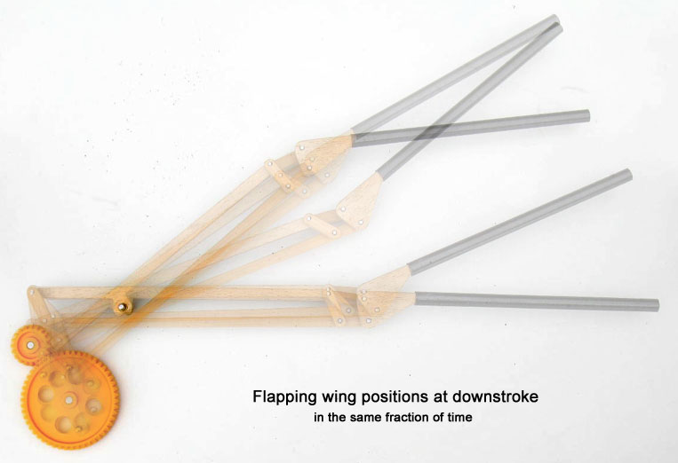
2.9 Oscillating stretched wing
Thrust also can be produced by raising and lowering a stretched wing in flight. But thereto the lift or the lift force during the upward motion must be smaller than during downward motion. The bigger the difference, the better for the thrust (please look at the principle of flight/vector diagram). Furthermore, a continual alignment of the angle of incidence is normally necessary.
Here a strikingly simple generation of an accordant oscillating motion of the wing by using an eccentrically pivoted rotating mass consisting of the mainspring and the gear. In this case the wing is aeroelastic twistable. The idea was coined by W. B. Mituritscha (probably from Russia, 1953).
Unfortunately, a forward and backward motion of the wing occurs along the way. However, this can be avoided by a second counter rotating mass.
There are diverse proposals to generate an oscillation motion of the wing by a pilot who is flying in a hang-glider or another ultralight aircraft - for example by fast press-ups or knee-bends.
Entirely different model experiments with oscillating
wings shows Karl-Heinz-Helling with his Double flapping wing airplane
(2008) related link 5.
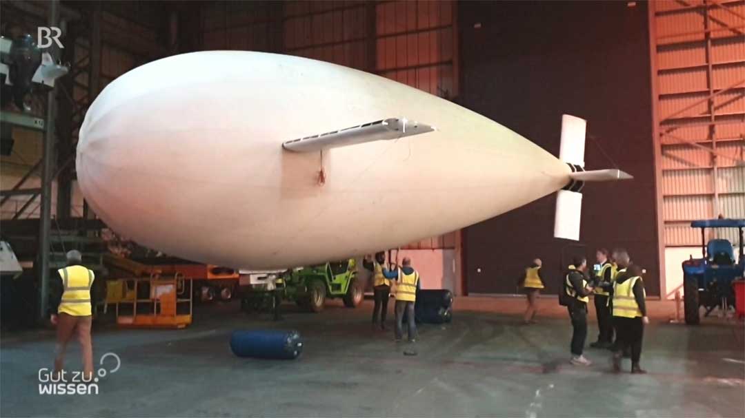
In principle, the driveless Zeppelin Phoenix
generates propulsion in
the same way with its wings, by its own up and down motions. British engineers
have developed it since 2016 (please look at related link
6). Also, hot-air balloons can become a little manoeuvrable with such
wings during ascent and descent.
2.10 Rotating wings
To avoid the accelerating forces in the final stroke positions
flapping wings
rotating on a cone-shaped shell where
sometimes built whose apex lies at the wing root.
The backward motion of the wing tip in the range of the lower end position is certainly disadvantageous for the lift.
the flight model by Horst Händler (1989). Both ends of the driveshaft are bended in Horst Händler's model. Thereon, the wings are attached freely twistable. The angle of incidence is guided by the upward pointing levers on the wings.
2.11 With non-twistable arm wing section

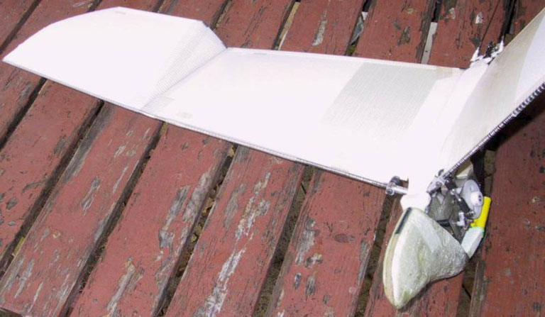
This is a membrane flapping wing by P. H. Spencer with a non-twistable arm wing section and passive twisting at hand wing section. From an aerodynamic point of view, however, there is still a kind of twisting in the area of the arm wing, due to the hand wing membrane connected at the rear. During downstroke it reduces and during upstroke it increases the lift on the arm wing. Eine Abwinklung des Handflügels nach unten hilft dabei. This indeed supports the lift shift, but requires negative lift in the whole hand wing area during wing upstroke.
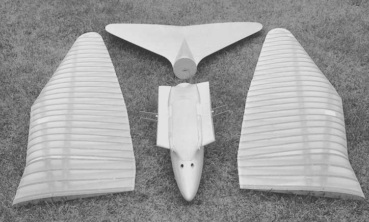
The arm wing is triangle shaped and has a large wing depth at the wing root.
Arm- and hand wing membrane overlap in wing span direction. Obviously, the
hand wing spar could make a little flap movement at the wrist. Later the hand
wing depth was enlarged (please look at the
construction of the pinion feather
by Alexander Lippisch).
This flapping wing design of the Seagull
was developed by Percival H. Spencer (USA 1958) (please look at related link 7).

Today, this flapping wing design principle is widely used, also with inserted sail battens.
3. Profiled flapping wings
Range of application
Profiled flapping wings or double-sided covered wings may work with a very high efficiency. With their mostly relatively low flapping frequency and the small operating range of lift coefficient of a simple airfoil not much thrust can be produced. Not, at least, if the full lift must be generated concurrently (flying with lift). Therefore, profiled flapping wings are suited especially for a level flight, the gently inclined climbing flight and of course for changing to gliding flight.
3.1 With artificial feathers
To ease the twisting, the closed airfoil can be fanning-out. So far, this is particularly used for large manned ornithopters.
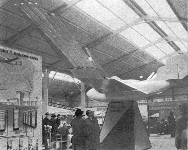
Adjacent, a flapping wing with staggered wing tips of the manned Schwan
1
, developed by Walther Filter (1955, at the Hannover fair 1958). The
angle of incidence deflection of the feathers
designed as several wings
was controllable. (please look at related link 8)
Even for splay and straddle movement of the feathers
there are old design proposals. In contrast, with
EV7b
only with simple feather implementations experiments have been
made.
A further example for artificial feathers is the
Icarus
by Emiel Hartman (England 1959).
A more recent experiment with artificial feathers is to be seen at the Birdman
Georges Fraisé (France 2005, please look at related
link 9).
3.2 With inclined hinge of the hand wing
A special version of a flapping wing derives from K. Herzog (1963). With this wing, the turning or the twist axis is not standing vertical to the stroke axis.
The arm wing should perform a flapping motion and a twisting motion at the shoulder joint. With rubber threads between arm- and hand wing the latter was pulled down a little (aeroelastic wing).
This is also an early suggestion for an articulated flapping wing with an additional flap movement of the hand wing.
The kink of the profile between the arm and the hand wing lies approximately at the same location as on the above mentioned membrane wing by P. H. Spencer.
3.3 Twisting by tilting the leading edge of the wing
The feature of the pitch propeller
by John
Drake lies in the twisting of the leading edge, not the
trailing edge of the flapping wing (England, flight tests
in 1978).
3.4 With stepped twisting

An approximate wing twisting can also be achieved by a stepped turning of relative non-twistable wing sections.
The model EV4 (1979) was also equipped with such a turning of single wing sections. But in this case, the turning was controlled by the wing drive.
A typical representative of a passive stepped twisted wing is
the Step-Twister
with his foam wings (Depron) by Karel
Pustka (2004). The developing gap between the wing sections is
covered with a membrane.
3.5 Twisting by stroke movement of the auxiliary spar
Here, the wing twisting is generated by a phase-delayed stroke movement of the main and auxiliary spar - developed by Emile Räuber (France 1909).
This technology was also used at the EV2 (1976). In the margin, the wings with their two spars powered separately are to be seen.
The function is similar to the wing of a Dragonfly. Here, too, the phase-delayed flapping movement of the main and auxiliary spar determines the amount of the wing twisting.

Furthermore, the Dragonfly obviously works with a strong spar at the leading edge. With the phase-delayed flapping movement of three spars the camber of the airfoil can be influenced, too.
The supports or linkages of the three spars at the body are clearly recognizable as dark, partly crossing structures at the back of the Dragonfly (please look also at related link 10).
In my experience, the twisting method is only suitable for small spans (about 1 meter). Otherwise the adherence to a certain twisting is undetermined by the elasticity, tolerances and friction of the components.
3.6 Servo controlled wing twisting
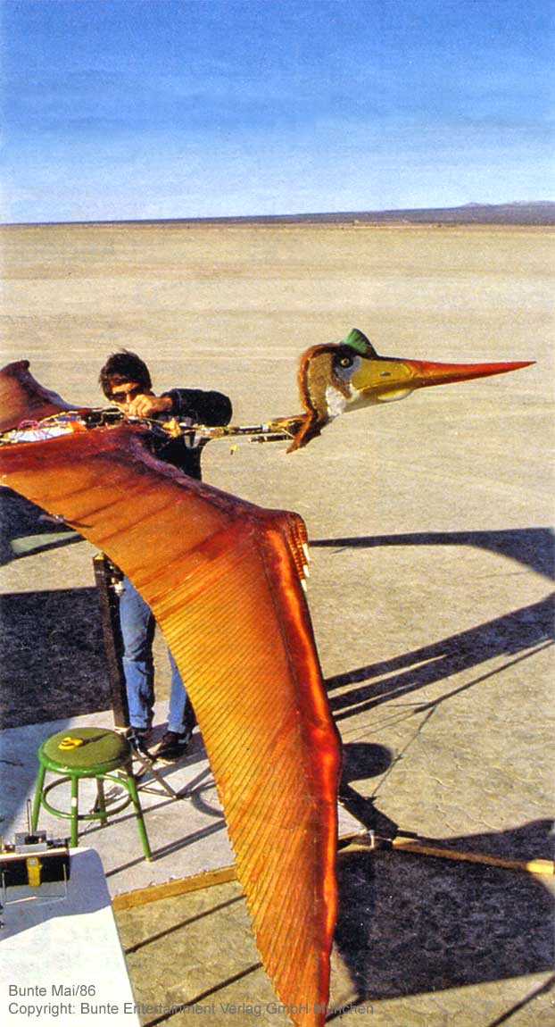
This is a lifelike and airworthy half-size replica of pterosaurs - a
Quetzalcoatlus Northropi (QN).
The aerodynamics of this ornithopter should equate the original as far
as possible. The idea comes from the creative genius Paul MacCready Ph.D.
(USA 1985).
The twisting of the wings was controlled by servos and the flight attitude was stabilized by backward and forward motions of the wing tips and nodding motions of the head.
For details - including the principle of the drive mechanism - please look
to the articles (in German) about the project by ![]() Paul MacCready and for further information
via related link 11
Paul MacCready and for further information
via related link 11
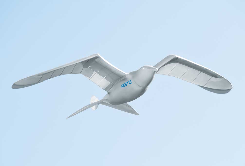
Also at SmartBird
by the company Festo the twisting of each wing side
is controlled by a servo (2011). However, in this case only the twisting of
the hand section of the wing is controllable. The inner arm section is not
twistable. There, the lift during upstroke is therefore very small - despite
bending of the hand wing.
The wingspan of the model is 2.0 meters, weight 0.450 kg, wing loading 9 N/sqm.
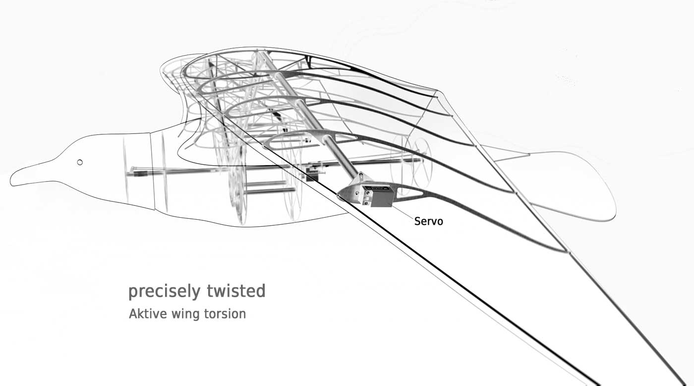
The wing covering is made of a 2 mm extruded Polyurethane foam plate which is formed to an airfoil (the cross section of the wing used at the model differs from the here shown wing ribs). Upper and lower side of this covering are not glued together at the rear end. So they can slide against each other and the wing is able to do twisting motion without folds (please look at the Shearflex principle in the next section).
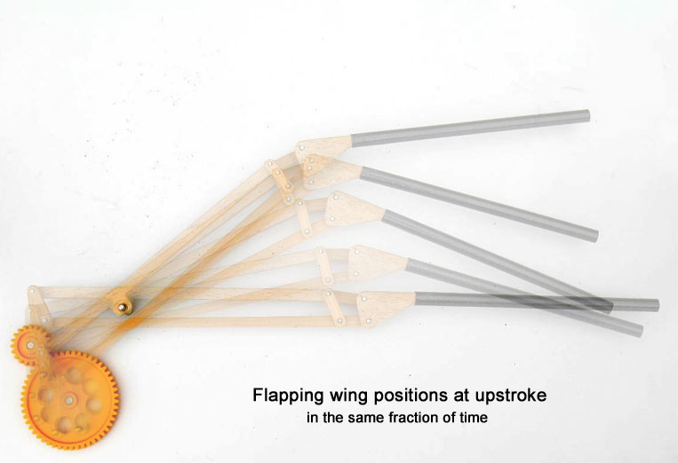
On SmartBird it is noticeable that the wing mechanism imitates the bending between arm and hand section of bird wings. The accompanying images show a basic structure of the flapping wing mechanism during up and down stroke. You also can see an animation (2.1MB) of it.
For further details about the SmartBird project please look at related link 12
3.7 Shearflex principle

Here an aeroelastic twistable profiled flapping wing according to the Shearflex Principle. This system makes a relatively inelastic covering applicable. If the twisting along the wing is constant and not to excessive, the airfoil contour accuracy is therefore very good.
Here, the twist elasticity will mainly be determinate by the spar designed
as wing leading edge.
This system was invented by Professor
![]() James
D. DeLaurier and Jeremy M. Harris (Canada 1994).
James
D. DeLaurier and Jeremy M. Harris (Canada 1994).
The ornithopter with its tripartition of the flapping wing is interesting, too. Jeremy M. Harris 1977 has applied it for patent.
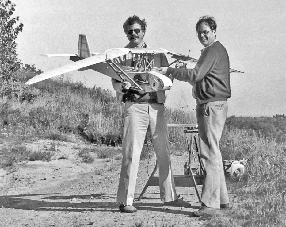
On the adjacent photo James D. DeLaurier and Jeremy M. Harris can be seen with their remote-controlled model, 3 m in span and with combustion motor. A sustained flight was achieved 1991. A video is available (please look at related link 13).
Here, a corresponding replica with an electrical drive system by Horst Händler (1994).
3.8 Oscillating wing tips
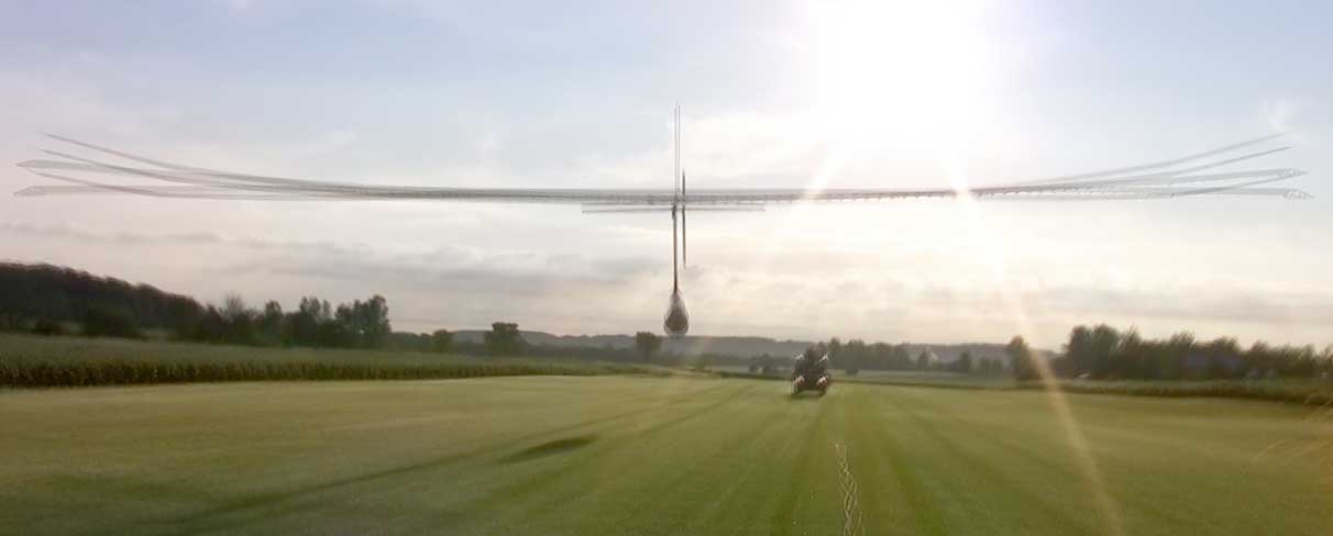
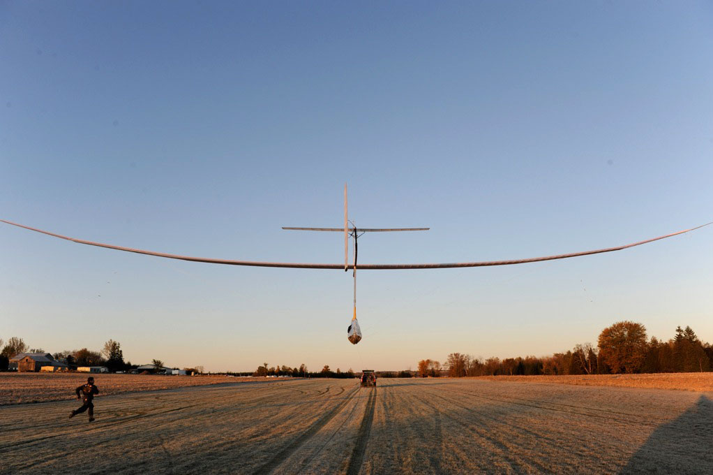
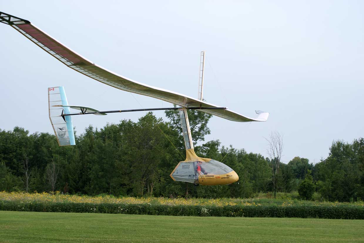
The main spar of the Snowbird
has no hinge, and instead flexes to produce the desired flapping motion.
By this way the wing tips perform an oscillating motion. Thereby the wing twists
passively under aerodynamic loads.
The principle of a wire powered wing oscillation has some marked advantages particularly for man powered ornithopters:
- fail-safe wing position for gliding
- applicable for large wing spans with its accordingly low induced drag
- very few moving parts
Todd Reichert has played an important role in developing of the Snowbird
and he also has flown it successfully. It was the world`s first officially
certifieded short flight of a human-powered ornithopter (Canada 2010).
For more information about the Human-Powered Ornithopter (HPO) Project Snowbird
please look at related link 14.
3.9 Shell wing

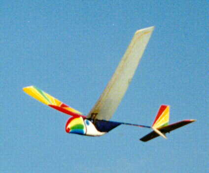
A wing with an active wing twisting by a drive controlled spar turning, developed by Albert Kempf (France 1998), please take a look at related link 15.
Apparently, the upper side of the wing consists of a cambered hard shell, which is shaped with foam on the lower side to a profiled airfoil wing.
A long thin plate with a cambered cross section
may be twisted easily and wrinkle-free. Also the aforesaid Shearflex principle
is using this property. This flapping wing category here is called shell
wing
.
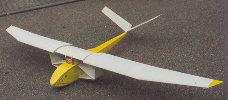
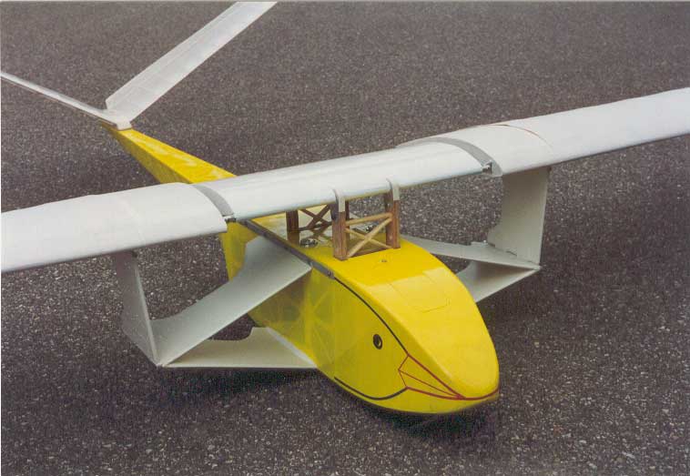
Such equipped Truefly
is to be seen in
the adjacent picture - an ornithopter with a wonderful flying sight. It
also was the first ornithopter which achieved strong climbing flights
with profiled flapping wings.
4. Notes
In the essay Flapping
Wing Designs
(in German, PDF 1.8MB) can be found additional informations about
these flapping wing constructions.
In conjunction with the EV-models developed
flapping wings are to find on the site: Articulated
flapping wings
.
The wings of pterosaurs have worked differently than today's bird wings, please look at Wing-function of flying saurian.
Ideas and suggestions for a further development are enclosed in the paper Lift during wing upstroke, version 10.1, (PDF 1.0 MB).
5. Related Links
to other flapping wing designs
- Alphonse Pénaud, (1850 - 1880):
https://web.archive.org/web/20190321124850/http://www.ctie.monash.edu.au/hargrave/penaud.html - Video about a flapping wing model by Cenek Chalupsky:
http://ovirc.free.fr/Clips_video.php - Construction method of the flying wing model by Jean-Louis Solignac:
http://ovirc1.free.fr/solignac-ornitho.htm - Thrust-Wing model ENTOID by Velko T. Velkov:
http://velkovelkov.blogspot.com/2009/09/entoid.html - The
Double flapping wing airplane
by Karl-Heinz Helling is flying:
https://www.modellbau-thiele.de/schlagfluegel.htm
http://www.mfc-rossendorf.de/fileadmin/user_upload/Projekt/Hubfluegel/Projekt/SchlagfluegelProjekt.htm - Zeppelin without drive motor
The Phoenix UAV
developed by the Centre for Process Innovation, National Printable Electronics Centre.
In the video from the spot 19:29 (in German):
https://www.br.de/mediathek/video/gut-zu-wissen-19102019-pakete-per-lastenrad-stand-up-paddling-und-zugvoegel-fliegen-ohne-motor-av:5d78dc721f300600137ecc7c - Report about Percival H. Spencer:
http://www.seabee.info/spencer.htm - The
Schwan 1
by Walther Filter in the Aviation Museum Hannover-Laatzen,
point of view atAir-Britain
:
https://abpic.co.uk/pictures/view/1166050 - Fanning-out wings of the
Birdman
Georges Fraisé:
http://ovirc.free.fr/GFraise.php - Close-up view of an orange colored Dragonfly:
http://www.grahamowengallery.com/photography/dragonfly_photography.html - Replicating of a pterosaurs by Paul McCready,
http://ovirc.free.fr/McCready.php
The Great Pterodactyl Project:
http://calteches.library.caltech.edu/596/2/MacCready.pdf (1.6MB) SmartBird
by the German company Festo (factory and process automation):
https://www.festo.com/group/de/cms/10238.htm- Video of the proof-of-concept model for a manned ornithopter flight
by James D. DeLaurier:
http://www.ornithopter.net/MediaGallery/Videos/index_e.html - Human-Powered Ornithopter (HPO) Project
Snowbird
by Todd Reichert:
http://hpo.ornithopter.net/
Technical informations with a general drawing of theSnowbird
:
http://www.aerovelo.com/snowbird-technical-info/
Todd Reichert's doctoral research studyKinematic Optimization in Birds, Bats and Ornithopters
https://tspace.library.utoronto.ca/handle/1807/31913 - Ornithopter model
Truefly
by Albert Kempf:
http://truefly.chez.com/