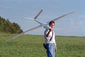
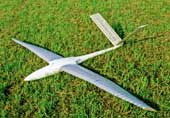
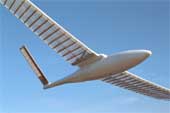
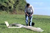
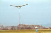
Ornithoptermodel EV7
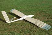
1. Ornithopter model EV7a
- first flight
- wing span
- weight
- wing area
- wing loading
- aspect ratio
- airfoil
- stroke cycle
- flapping angle
- 1989
- 3.14 m
- 4.6 kg
- 0.9 sq m
- 5.1 kg/sq m
- 10.5
- CLARK Y (11,7)
- 0.6 sec
- 53 deg
- [124 in]
- [162 oz]
- [1398 sq in]
- [16.7 oz/sq ft]
Wing twisting
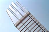
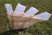
At the EV7a again was used aeroelastic twisting
along the whole wing. At rest the wing takes the twist position of the upstroke
(look also at the preceding picture).
Wing root fairing
No inclination of the stroke plane applied. Therefore, a kink results in the
trailing edge at the transition between the rotational symmetric wing adapter
roller and the airfoil of the wing (please see handbook,
chapter 8.8).
1.1 Pictures of the flying EV7a
Inflating the airpring
Before the start the gas pressure spring is pumped up. By the pressure you
may control the flapping time comparison between the upstroke and downstroke.
At the EV-models mostly was aimed for ratio 1:1.
High start
With the EV7a ornithopter high starts with a rubber
cord were carried out for the first time. A height of about 10 meters was
enough. To do this the mechanism must be locked in glide position (please
see Rack and pinion drive system).
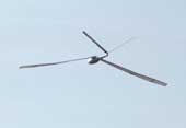
Twisting of the wing during the downstroke
On the inner arm wing the twisting is approximately correct. But from today's
view wing twisting is inadequate near the wing tips. Refer to the following:
- - Report about The development of the EV- flapping wing models, figure 26 (in German, PDF 1.4 MB)
- - Handbook, chapter 6.5 (without photos, in German, PDF 3.3 MB)
Overshoot of the angle of attack
(Annotation like corresponded picture
of EV6 )
At the end of the strokes in the hand wing the twisting increases too much.
This is mainly caused by the inertia of the trailing edge when slowing down
the stroke motion and when accelerating in the opposite direction.
When the wing comes to a standstill at the end of the stroke, in the interest of lift and thrust the angle of attack should be like gliding. But there are also small advantages to the overshooting (see handbook, chapter 6.8 and 6.9).
Long distance flight
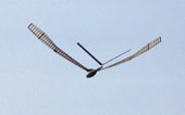
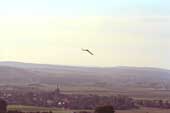
This is one of the original photos whose display details with the model were
composed to a strip. All display details was composed in correct positional
arrangement by land marks.
-

- Flight pictures in large size (136 KB)
1.2 Flight stability of ornithopters
With all EV-ornithopters the powered flights often had to be interrupted prematurely because the ornithopters lost their flight stability. Causes include the following:
- Loss of stabilizing force due to changes in the air speed or the angle of climb.
- Lacking practice und nervousness of the pilot.
- Visibility problems because far distance or large turning radius.
Probably the constantly changing longitudinal dihedral by the wing pitching and twisting has a part of this. In any case, in nearly all EV ornithopter models the horizontal stabilizers were too small after a new design was built.
The unstable forces of a flapping wing by variation of the speed could also duplicated by calculation (please look at the handbook, chapter 8.6).
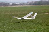
The stability problems are apparent from the varying presentation of the fuselage in some of the following pictures of a circle flight.
In the flight tests I often have made the experience that the model changeover to descent with the increase of the flapping frequency. At that time, I had always only led this back to an insufficient wing twist and a stall in the outer wing area, especially during wing downstroke. This also can happen during wing upstroke. With a stall, thrust and lift are simultaneously reduced. But there are also other possible causes for this flight behaviour.
One of them is the shift of the centre of lift during wing upstroke. If during upstroke the lift near the wing tip is perhaps only slightly negative at first, it becomes even more negative when the stroke speed increases. Since the lift near the wing root remains nearly the same, this corresponds to a shift of lift towards the wing root.This increases the thrust, but reduces the lift. In this way, the model goes into descent flight, despite the increase in thrust. Only when the flapping frequency is further increased, it comes to a stall on upstroke.
The reduction in lift during upstroke due to the displacement of lift can be compensated by larger lift during downstroke or by height control. For this purpose, however, the wing profile must have sufficient lift reserves (e.g. by large wing depth). This was obviously not the case with my models.
In addition, when the flapping frequency is increased, the inclination of the lift force along the wing becomes greater. On upstroke it inclines more backwards and on downstroke more forwards. This increases the thrust, but reduces the lift. If the greater thrust is used to increase airspeed, lift can increase again. However, the increase in speed is not abrupt. It takes a certain amount of time, especially with heavy models. During this acceleration time the lift is still too small and the model loses height. To avoid this effect, the flapping frequency should only be increased in small steps or very slowly. However, corresponding tests were not carried out at that time.
Therefore, an increase in the flapping frequency does not guarantee a climb flight. Unfortunately, in my models also a reduction in the flapping frequency did not lead to more climb. The window of the optimal flapping frequency simply was too small. According to more recent findings, the EV7 model probably flew more in cruising flight than in distance flight mode. Thereby, the distribution of lift during upstroke is completely different than originally intended (please see the diagram of lift distributions on the site Gait change).
1.3 Videos of the EV7a (1990)

Scene 1:
It shows a short powered flight with a changing to gliding flight. Thereby, a rack-and-pinion drive system with an electronic switch was used.
| Download |
|
640 x 480 mp4 (0.8MB) |
|
480 x 360 mp4 (0.5MB) |
|
320 x 240 mp4 (0.2MB) |
Scene 2:
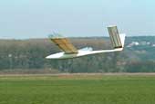
In this powered flight the cyclical changes of the wing twisting is clearly to be seen.
| Download |
|
640 x 480 mp4 (0.5MB) |
|
480 x 360 mp4 (0.3MB) |
|
320 x 240 mp4 (0.1MB) |
Scene 3:
With a length of about one minute it shows one of
the few longer flights.
In particular one can see:
- a high start to a height of about 10 meters,
- a changing from gliding flight to powered flight with a rack and pinion drive unit,
- the relatively slow stroke motion with a stroke cycle of about 1.1 s,
- nevertheless there is only to be seen a little bobbing up and down of the fuselage,
- a horizontal flight over a longer distance without upcurrent due to a slope or thermal and
- the result of the breakdown of lift and thrust due to stalling after a short climb. For details please look above to the chapter Flight stability of ornithopters.
| Download |
|
640 x 480 mp4 (1.3MB) |
|
480 x 360 mp4 (0.7MB) |
|
320 x 240 mp4 (0.4MB) |
2. EV7b with primary feathers
- first flight
- wing span
- weight
- wing area
- wing loading
- aspect ratio
- airfoil
- 1992
- 3.20 m
- 4.8 kg
- 0.94 sq m
- 5.1 kg/sq m
- 10
- NACA 4412
- [126 in]
- [169 oz]
- [1459 sq in]
- [16.7 oz/sq ft]
Wing with feathers
To enlarge the wing twisting near the wing tips experiments with feathers
have been made. The twisting of each wing feather should be significantly
larger than in the case of the continuous airfoil - especially during the
downstroke.
The feathers were not designed to decrease the induced drag, because that would be too difficult.
Primary feathers in gliding flight
The connection line of the feather tips
corresponded to the ideas of
the designer. The feather tips continued the camber and twisting of the hand
wing.
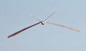
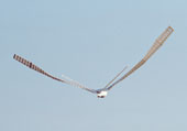
In powered flight (in direction of down stroke) the bending of the feathers
was often quite variable as seen in the following fly-by of an ornithopter
.
Usually it is quite useful in gliding. Also the wing twisting was alright.
Flight in dawn
The pixel-aligned adjustment of the picture series only can be made by using landmarks.
Therefore the last two pictures of the flapping wing vehicle with feathers are
only approximately correct.
-

- Sequence in large size (321 KB)
Fly-by of an ornithopter
These pictures of a photo series of an ornithopter in flight are composed in an
arbitrary manner.
-

- Sequence in large size (335 KB)
2.1 Three meter bird on approach
- an aero modellers highlight -
Following pictures show the EV7b model (with feathers at the wing tip) during approach. With a few wing strokes it overcomes large distances (in this case nine wing beats). The different twisting of the wing during up- and downstroke can be well detected.
3. Ornithopter model EV7c
- first flight
- wing span
- weight
- wing area
- wing loading
- aspect ratio
- airfoil of arm wing
- airfoil at the wing tip
- 1994
- 2.94 m
- 4.7 kg
- 0.9 sq m
- 5.2 kg/sq m
- 11.3
- S1020
- E203
- [116 in]
- [166 oz]
- [1401 sq in]
- [17 oz/sq ft]
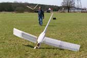
This was a relatively harmless landing without the tail unit after the last flight of the EV7c in 1995. The new wing mechanism which replaced the auxiliary spar of the hand wing was not successful.

