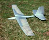
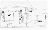
Ornithopter model EV4
Content:
- first flight
- wing span
- weight
- wing area
- wing loading
- aspect ratio
- airfoil
- 1980
- 3.06 m
- 4.8 kg
- 0.84 sq m
- 5.7 kg/sq m
- 10
like bird
- [120 in]
- [169 oz]
- [1305 sq in]
- [18.7 oz/sq ft]
The arm and hand wing sections were actively pitch controlled separately from the drive at the relevant section root. The arm wings were rigid. The hand wings should be twisted aeroelastic. The twisting of the hand wing was appropriate for gliding.
1. Start preliminary
Adjusting works
The pitch of the hand wing could be modified in a small range.
At the wing root fairing one can see the high camber of the like bird
airfoil.
2. Flight photographs
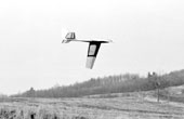
EV4 with stepped
wing twisting
at the downstroke of the wing. The torsion of the arm and hand wing is good too seen.
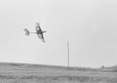
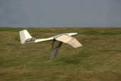
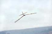
EV4 in flight
during wing down stroke. In the area of the hand wing you can see a small
aeroelastic twisting. During powered flight, the twisting of the hand wings
has been too small. During the downstroke, especially near the wing tips,
the angle of incidence were not enough negative. But at that time, definite
theoretical instruction about the distribution of this angle along the span
was missing (e.g. 2001, handbook, chapter 6.5 to
6.7).
3. Driving mechanism of the EV4
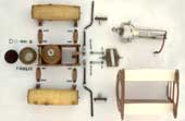
From right towards left in the picture:
- Drive unit with a cardan gear mechanism. It is the same like in the model EV1. Main and control pins are provided with sliding blocks of polyamide. For specification of the cardan gear mechanism please look at the report about The development of the EV- flapping wing models (in German, PDF 1.4MB). You also can see an animation of the cardan gear mechanism.
- Main frame of the mechanism with side panels of rigid foam to adjust to the surface of the fuselage also made of rigid foam rings.
- Sloped control scotch yoke, made of 1 mm epoxy plates and slide of steel. The slot is at an angle with the axis of the slider like the path line of the control crank pin in the glide situation.
- 2 rods with spherical bearings
- Lever arms to control the inner wing pitch, mounts onto the wing axis.
- Wing axis was made of 6 mm spring steel, offset for a favourable fuselage-wing transition.
- Wing adapter rollers (of the EV8) made of rigid foam and plywood and covered with epoxy-glass laminate, each with two inner 45 mm long lever arms.
- 4 plywood linkages
Swing
(frame of plywood) with the pressure vessel (about 5 bar) for the pneumatically spring made of epoxy-glass laminate. Ahead the frame is made of the main scotch yoke. At it are mounted the bearings for the control scotch yoke.- Cylinder or support ring made of epoxy-glass laminate, for the long-stroke bellows-like rolling-diaphragm below.
- The piston of the pneumatic spring stands at the bottom of the fuselage and is not shown here.
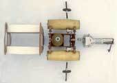
Components mounted
The linkages for an active twisting of the wings are good to see:
- - from the control scotch yoke,
- - over the rods with spherical bearings,
- - to the inner pitch lever arm of the wing shaft,
- - to the outer pitch lever arm of the wing shaft.
The relative motion between the wing root and the wing root fairing more over was used, via a linkage in the arm wing, to actively twist the hand wing root.
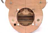
Bottom view
There is visible the opening for the piston of the long-stroke rolling diaphragm.
It stands at the bottom of the fuselage.
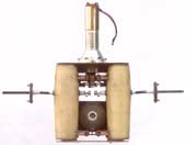
Front view
In the opening, behind the horizontally running main scotch yoke (with slide of steel) the inclined slide of the control scotch yoke is still recognizable.
4. Video of the EV4 (1979)

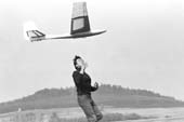
Though the powered flights took somewhat longer than on the EV1, all in all only about five flights had been completed - a little sparse for the work in years. But there had been just too many ideas for further improvements.
| Download |
640 x 480 mp4 (0.7MB) |
480 x 360 mp4 (0.4MB) |
320 x 240 mp4 (0.2MB) |

