Gewrichts-slagvleugel
Beschijving van de slagvleugelconstructies
die gelijktijdig met de EV-modellen ontwikkeld werden
Inhoud:
- 1. Eisen aan een slagvleugel
- 2. Aëro-elastisch gestuurde gewrichtsslagvleugel
- 3. Slagvleugel met instelbaar torsiemoment
- 4. Slagvleugel met toenemende
vleugelverdraaiing nabij de vleugeltip - 5. Aëro-elastisch gestuurde
gewrichts-
slagvleugel met instelbaar torsiemoment en
verdraaiingstoename nabij de vleugeltips - 6. Vleugelbekleding van de slagvleugel
- 7. Polsgewricht voor een
sterke passieve buiging
van de handvleugel (in het Engels) - 8. Externe Links
1. Eisen aan een slagvleugel
De constructieve eisen aan een slagvleugel bestaan onder andere uit de theoretische
verdeling van de liftcoëfficiënten volgens ![]() Robert T. Jones (USA 1950 en 1980) en de
daarbij benodigde instelhoek langs de halve spanwijdte.
Robert T. Jones (USA 1950 en 1980) en de
daarbij benodigde instelhoek langs de halve spanwijdte.
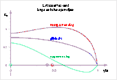
Hier zijn bijvoorbeeld de betreffende, vérgaand geoptimaliseerde gedragingen
voor een vlakke stijgvlucht van een rechthoekige slagvleugel met het allround-profiel
CLARK-Y afgebeeld. (Voor principes zie Handboek).
De instelhoek bij de vleugelwortel blijft in dit geval constant tijdens de
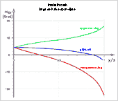
gehele slagperiode. De verdelingen van de zogwinden langs de spanwijdte zijn
in alle gevallen rechtlijnig (zie diagram Zogwindverdelingen
).
Bij de slagvleugelconstructies spelen bovendien nog de gewicht en de traagheidsmomenten om de slag- en om de draai-as van de slagvleugel een grote rol.
There are recent findings about flying with relative constant lift resp. with wing turning during upstroke. If one is concerned with the construction of a flapping wing, one should also get to know the advantages and disadvantages of this way of flying. In particular, the long distance flight can be improved by the wing turning (please see Flapping wings with and without wing turning in German, PDF 0.7 MB).
2. Aëro-elastisch gestuurde gewrichts-slagvleugel
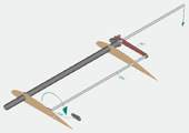
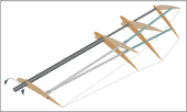
Principiële liggeruitvoering van een
slagvleugel voor profielen met bekende profielpolaren
met een gewricht voor een aanvullende slagbeweging van de handvleugelligger.
Deze laatste wordt door een veer naar beneden getrokken (veerconstructie is
hier niet afgebeeld, zie Gewrichtsslagvleugel
in het Duits, PDF 1.3 MB).
- Gedurende de glijvlucht, met zijn gemiddelde liftkracht, neemt de handvleugel de gestrekte middenpositie in.
- Bij de neergaande slag worden de liftkrachten in het handvleugelbereik beduidend groter en de handvleugel slaat tegen de veerkracht in naar boven.
- Als bij de opgaande slag de liftkrachten ontbreken dan trekt de veer de handvleugel naar beneden.
De van kleine, aërodynamische krachten afhankelijke- en daarmee aëro-elastische slagbeweging van de handvleugel, wordt door de hefboom ( bruin voor armvleugel en groen voor handvleugel) voor de besturing van de verdraaiing langs de hele vleugel gebruikt. Op die manier ontstaat er een gewrichtsslagvleugel met aëro-elastisch gestuurde verdraaiing. De werking komt een beetje overeen met die van een vogelvleugel.
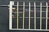
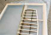
Met uitzondering van de vleugelwortelrib worden alle ribben vrij draaibaar
op de ligger geplaatst. Als slagvleugelbekleding is hier de elastische Polyurethaan-folie
Platilon U 04
toegepast (zie
externe link 1).
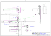
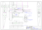
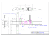
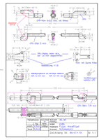
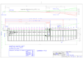
Technische tekening voor één slagvleugel polsgewricht met een
kleine hoek van de handvleugel,
voor een kruisvlucht
Polsgewricht met arm-vleugel twist hendel
en trek met kabel voor het vergrendelen van de vleugel twist in glijden.
Het principe van deze aëro-elastische gewrichtsslagvleugel werd gelijktijdig met het model EV6 (1983) ontwikkeld en ook bij mijn volgende modellen steeds opnieuw toegepast.
3. Slagvleugel met instelbaar torsiemoment
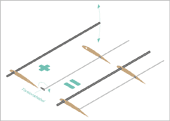
Door verdeling van de slag- en verdraaiingsbewegingen van een slagvleugel over de hoofd- en de hulpligger is het verdraaiingmoment in te stellen.
Hiernaast wordt de samenhang tussen de liggerconstructie van een aëro-elastisch
verdraaibare slagvleugel met een instelbaar draaimoment verduidelijkt. De
instelling geschiedt met behulp van een draaimomenthefboom
die aan
de vleugelwortel gemonteerd is.
De overige, hier niet afgebeelde, ribben worden vrij draaibaar op de liggers gemonteerd. De bekleding wordt uitgevoerd met een elastische folie of op basis van het principe van verdraaiing door verschuiven (van de achterlijsten). Ook schil- en hardschuimvleugels kan men op deze manier instelbaar maken.
Past men dit systeem toe bij een normale, geen op- en neerslaande, vleugel, een propellerblad of een molenwiek toe dan is deze verdraaiing met de betreffende hulpligger te besturen.
De verschillende vleugelsystemen
zijn op vele manieren met elkaar combineren. In de afbeelding hiernaast wordt
bijvoorbeeld bij een aëro-elastisch gestuurde gewrichtsslagvleugel de
hulpligger van de handvleugel met zijn draaimoment als veermechanisme voor
de kleine slagbeweging van de handvleugelligger toegepast.
De torsiehefboom van de armvleugel (AT) en de hulpligger (AHi) van de armvleugel zijn dan vast met elkaar verbonden. Het draaimoment van de hefboom wordt op deze manier naar een draaimoment op de hulpligger omgezet. Deze is aan de voorzijde bevestigd en drukt de handvleugelligger in de aangegeven richting naar beneden. De drukkracht wordt met de binnenhefboom (InH) aan de vleugelwortel ingesteld.
Het geprofileerde armdeel van deze gewrichtsslagvleugel is ook met een membraan-handvleugel te combineren. Dit is mogelijk een goede uitvoering van een slagvleugelmodel voor gemiddelde stijg- en glijvluchten.
4. Slagvleugel met toenemende vleugelverdraaiing nabij de vleugeltip
Dit is de manier waarop
de slagvergrotende vleugelligger
.
Dit mechanisme is zowel bij de hoofd- als de hulpliggers toe te passen.
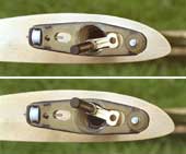
Stangenstelsel boven:
Schiuifstangenstelsel gedemonteerd.
Stangenstelsel
onder:
Schuifstangenstelsel gemonteerd.
Het linker scharnier dient hier als basis. Bij een slagbeweging van de middelste schuifstang, hier naar beneden gericht, zorgt ervoor dat het buitenste rechte liggerdeel een vergrote slagbeweging uitvoert.
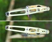
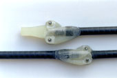
GFK-scharnier van de schuifligger
met verschillende asafstanden voor de overbrenging (1:1,5) van de slagbeweging.
Hiernaast staat de liggerconstructie van een slagvleugel voor actieve verdraaiing in het armvleugelgebied door middel van her verdraaien van de hoofdligger.
Er is een slagvergrotende hulpligger toegepast. Daardoor neem de verdraaiing van het handvleugelbereik toe. Het schuifstangenstelsel van de liggers is hier co-axiaal ingebouwd. Alle andere ribben worden vrij draaibaar op de liggers gemonteerd. De bekleding wordt uitgevoerd met een elastische folie.
De ribbe bij het handgewricht is vast op de hoofdligger en de het lager van de hulpligger is vast met de wortelribbe verbonden. Alle andere ribben zijn vrij draaibaar op de ligger gemonteerd. De bekleding van de vleugel wordt uitgevoerd met elastische folie.
Voor een passieve of aëro-elastische verdraaiing moet de ribbe van het handgewricht draaibaar om de hoofdligger gemonteerd worden.
5. Aëro-elastisch gestuurde gewrichts-slagvleugel met instelbaar torsiemoment en verdraaiingstoename nabij de vleugeltips
Een ribbenvleugel van het model EV8, uitgevoerd als aëro-elastisch gestuurde gewrichtsslagvleugel, gecombineerd met een slaghoek vergrotende hulpligger in het vleugeltipgebied. In order to achieve also a good glide, the wing was designed without lift reserves, i.e. without increased wing depth.
- De verdraaiingelasticiteit van deze slagvleugel is door het hulpliggermoment van de armvleugel bij de vleugelwortel in te stellen.
- De verdraaiing tijdens de neergaande slag wordt door een stootdemper afgeremd.
- De verdraaiing voor de glijvlucht wordt door een RG-bestuurde servo gefixeerd.
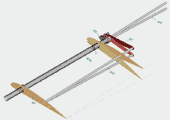
De verdraaiing tijdens de opgaande slag komt hier tot aan de de vleugeltips met de theoretische waarden overeen (zie ook de afbeelding van de Ruwe opbouw van de vleugel van de EV8). De grote massatraagheid van de slagvleugels om zijn slag- en verdraaiingsas, oefenen nog steeds een storende invloed uit op het bewegingspatroon.
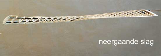

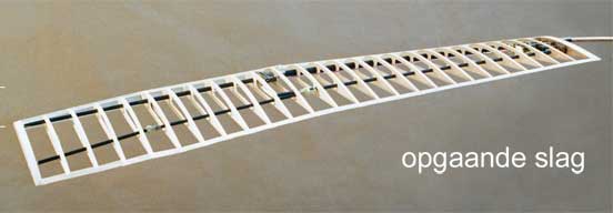
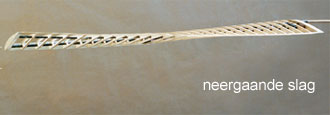
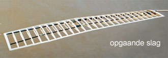
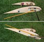
Maximale geplande verdraaiing van de vleugel (de afbeelding aanklikken)
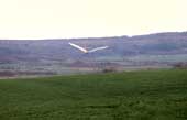
De gewricht-slagvleugel heeft in de vliegpraktijk een een groot voordeel. De afwikkeling van de handvleugel t.o.v. de armvleugel is afhankelijk van de lift van de handvleugel. Gelijktijdig bepaalt dit het instelverloop langs de spanwijdte. Als ook op de opnames van de vlucht de grootte van het verloop te herkennen is, dan is de grootte van de lift van de handvleugel t.o.v de glijvlucht d.m.v afschatten te bepalen. Bovendien kan eenvoudig op het instelverloop ten tijde van de opname gesloten worden (zie de afbeeldingen van de EV6 en de EV7). Met deze beide gegevens zijn de bedoelde instellingen van het slagvleugeldraaimoment, het aandrijfvermogen en van de slagtijdverhoudingen mogelijk. In het bijzonder zijn m.n. de afbeeldingen van de vlucht zo ongeveer in het midden van de vleugelslag zeer leerzaam.
Verwijzing
In het volgende artikel vindt u nog wat meer details over de: Gewrichtsslagvleugel (in het Duits, PDF 1.3 MB).
Informations and suggestions for a further development you will also find in the article Lift during wing upstroke, versie 10.1, (Engelse versie, PDF 1,0 MB).
6. Vleugelbekleding van de slagvleugel
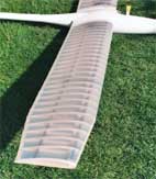
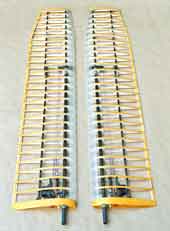
Net als bij de andere EV-modellen werd voor de hierboven genoemde vleugel als bekleding een 0,05 mm dikke, rekbare Poly-Eruthaan-folie toegepast.
Voor de verbinding tussen het vleugelraamwerk en de bespanfolie wordt dubbelzijdig plakband toegepast.
Eindlijstvariant voor de slagvleugel
Bestaande uit vissnoer aan de achterlijst, dat met plakband is vastgemaakt.
At the end of the balsa rib is inserted a tab made of k GRP with a hole. To
make the tab, place a straight wire on a thin glass silk and fold glass silk
around the wire After curing, pull out wire.
Hier volgt de beschrijving van de werkwijze voor
Het bespannen van een slagvleugel met een elastische folie
(in het Duits, PDF 360 KB)
7. Polsgewricht voor een sterke passieve buiging van de handvleugel
(Ik ken helaas geen Nederlands,
dus in het Engels)
The downward bending of the hand wing during the upstroke in distance flight especially supports the
- reduction of the induced drag,
- avoidance of large negative angles of attack in the outer wing area,
- enlargement and equalization of the lift of a whole flapping period,
- concentration of the lift in the centre of the span and thus enhancement of the thrust, and the
- facilitation of the motion reversal of the wing in the stroke end positions.
Aerodynamically, the bending of the hand wing is particularly advantageous if the lift is high in the arm wing area during upstroke, e.g. due to a turning of the wing root.
7.1 Mode of operation of the bending
The single effects of a strong bending of the hand wing during upstroke in distancevlucht can be described as follows.
- During upstroke the oncoming flow to the wing comes more from above. If it is able to give way downwards by the passive bending, its lift will no longer be as negative as with the stretched wing (please see the diagram lift distributions in distancevlucht). This makes the overall lift larger and the profile selection easier.
- At a wing there is always a flow along the wing due to different pressures along the wing. It causes the vortices behind the wing and thus the induced drag (please see diagram induced drag on the site Het Handboek ). This longitudinal flow is particularly strong when only the arm wing generates large positive lift. With its winglet effect, the bending decrease the longitudinal flow and thus reduces the induced drag. The longitudinal flow also becomes smaller because the lift in the hand wing area is no longer so strongly negative (please see point 1).
- From the large lift in the middle of the span, no more so much flows towards the wing tip. This helps with the concentration of lift in the middle of the span and thus with the generation of thrust.
- If the lift at the wrist is increased during the descent, e. g. as in the following image of the wrist, this also supports the concentration and enlargement of the lift in the centre of the span.
-
At the bended hand wing, a small oblique blow from above occurs. Thereby the lift is shifted a little bit along the hand wing in blowing direction, thus towards the wing tip. Birds strengthen this effect by pivoting the hand wing backwards (wing sweepback).
If there is positive lift at the wrist, negative lift is at least reduced by the oblique blowing, especially near the wing tip. This makes the profile selection easier. You can further enhance the effect by increasing the positive lift on the wrist during bending, e. g. as in the following image of the wrist.
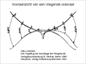
In birds, the sweepback of the hand wing is coupled with a sweepback of the forearm. The associated oblique blowing of the forearm supports the concentration of lift at mid-span.
There is still a lot of experimentation to be done with the application of the oblique blowing. But the wing profiles in birds indicate, that there are rarely any negative angles of attack due to bending and pivoting of the hand wing (please see drawing of wing shapes and cross sections by Karl Herzhg).
- The possibility to use the wind turbine energy of the arm wing for thrust generation in the outer wing area is strongly limited. The hand wing reduces its stroke path by bending and changes its direction of action. Furthermore, the negative lift is very small. Whether the acceleration of the wing mass upwards, and there an end position spring, can absorb the whole wind turbine energy, must be checked. Otherwise, a compensation spring is appropriate.
- With the bending, the sequence of wing twists in the individual wing sections can be coupled mechanically with the stroke motion near the stroke end positions. This supports the displacement of lift along the wing and thus the generation of thrust (please see chapter 7.3). In addition, it can be used to increase the lift during wing upstroke near the final stroke positions of the wing, thus without much working drag.
- The division of the flapping wing into two sections combined with the bending reduces the problems with mass inertia during the flapping motion in the area of the flapping end positions (please see Lift during wing upstroke, version 10.1, PDF 1.0 MB, chapter 7.3).
- The transition from the bent to the outstretched wing position begins, before
the arm wing reaches its upper final wing position. When the arm wing arrives
at the top, it should wait there, until the hand wing has reached the outstretched
wing position. Therefore, the drive should pause there for so long (please
see above paper
Lift during wing upstroke
, chapter 6.3, Fig. 20.).
The upstroke of the arm wing consists of a relatively fast upstroke motion, followed by a short waiting time in the upper stroke end position. - During take-off and landing with stretched wings a possible stroke movement of the wingtips must be considered.
- Even without a functional background, the bending during the flight of an ornithopter looks good. It increases the naturalness and liveliness of the stroke motion. It appears more harmonious.
- The calculations made here for lift, thrust, wing twisting etc. are no longer valid. One is again dependent on conjectures and on the method of trial and error, probably without measurements and comparison of intermediate results.
- With the bending of the hand wing described here, you can certainly achieve higher thrust values than without.
I only became aware now (2021) that the passive bending of the hand wing offers so many aerodynamic advantages. The engineering effort and the experimental requirements for the bending of the hand wing of an ornithopter are large. It has to be examined whether the various tasks can be solved in another way or can be done without it (e. g . by restricting to kruisvlucht).
7.2 Pivoting of the wrist axis
-
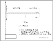
- Pivot angle κ (Kappa) of the wrist axis for an automatic increase of the angle of incidence of the hand wing by the bending
If one pivoted the wrist axis rear inward
one achieves an automatic increase
of the angle of incidence when bending the hand wing downwards (please see adjacent
drawing). In this way, the angle of incidence changes self-acting in the desired
direction at the beginning and end of the upstroke. This influence on the angle
of incidence can approximately replace or at least complement the twisting of
the hand wing during upstroke.
During the bending of the hand wing, its angle of incidence or angle of attack increases. Due to increasing lift, the bending comes to a standstill already after a short upstroke motion of the arm wing. Depending on the upstroke speed, this is the case with a different bending. In this way, the maximum size of the bending automatically adapts to the beat frequency. The higher the beat frequency, the greater is the bending.
In birds, a corresponding, but only small change in the angle of attack of the hand wing is steered by the arm wing. When the stretched position of the arm wing is reached, the angle of attack of the whole hand wing becomes somewhat smaller and relatively inflexible (glide position). When the arm wing leaves its stretched position, the angle of attack of the whole hand wing becomes a little larger and more flexible again. K. Herzog 1968 has not written anything about a change in the angle of attack of the hand wing during the bending movement.
The paper bird wing by Karl Herzog shows a feather fan extending from the wrist to the back. When angled down, this fan obviously overlaps the different setting angles of the adjacent wing areas.
-
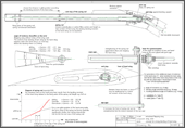
- Concept voor één slagvleugel polsgewricht met een sterke hoek
van de handvleugel,
voor een distancevlucht
If one inclines the wrist axis front downward
(please see adjacent drawing),
the tip of the hand wing is slightly pivoted backwards when the hand wing will
be angled downward, although not so far as in birds (tip-reversal upstroke). However,
the benefit of such a small pivoting motion backwards is not clearly visible.
By the drag resp. thrust near wingtip, probably only the force for bending downwards
is increased resp. reduced.
An example of an inclination and a pivoting angle of the wrist axis is shown in the concept drawing. The optimal size of these angles and their possible combinations must be determined by experiments. Unfortunately, there are no empirical values for this yet.
-
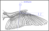
- Waarschijnlijke zwenkhoek van de handvleugel buigingsas bij de licht gestrekte vogelvleugel.
When determining the pivot angle of the bending axis of the hand wing, one can
orientate on the pivot angle of bi birds with slightly stretched wings. When the
wing is slightly stretched, as shown in the adjacent picture, I assume that the
bones of the hand are approximately perpendicular to the bending axis. Because
there are barely existing muscles for twisting or turning of the hand wing (please
see Anatomie van een vogel-vleugel en ![]() Karl Herzog, p. 46). However, the alignment
of the
Karl Herzog, p. 46). However, the alignment
of the axis
changes when stretching and pivoting the hand wing and possibly also
when bending strongly.
Due to the pivot angle, there occurs a small turning of the hand wing around its longitudinal axis when it is bent down. This makes the angle of attack large near the wrist. However, it still remains negative at the wingtip. This is exactly what is desired for the self-actuated bending. In addition, seen in the longitudinal direction of the wing, the large lift at the wrist supports the large lift at the arm wing. On the hand wing, therefore, its rotation is aerodynamically more advantageous than its twisting.
On upstroke with a barely recognizable bending, the elastic range at the beginning of the bending is already sufficient for changing the setting angle. There, the twisting of the hand wing is determined in particular by the widely together grown bones of the hand and by tendons.
With the articulated flapping wings used so far, it has
proven to be advantageous also to control the twisting of the arm wing by the
passive bending of the hand wing. In the above wrist-concept
drawing, therefore, the fuselage near part of the wrist was approximately
taken over from the above Aëro-elastisch gestuurde gewrichts-slagvleugel
(according to ![]() Karl Herzog, the wrist of birds is also divided
into two partial joints, a proximal ulnacarpal joint and a distal mediocarpal
joint). The necessary twist of the arm wing during up- and downstroke is thereby
already completely carried out during a small bending of the hand wingj, in the
close range of the stretched wing position (zie de click-afbeelding
boven an de Vlucht images van de EV7a).
If the hand wing bends further, the twisting of the arm wing remains unchanged.
This behaviour of the arm wing has advantages in shifting of lift.
Karl Herzog, the wrist of birds is also divided
into two partial joints, a proximal ulnacarpal joint and a distal mediocarpal
joint). The necessary twist of the arm wing during up- and downstroke is thereby
already completely carried out during a small bending of the hand wingj, in the
close range of the stretched wing position (zie de click-afbeelding
boven an de Vlucht images van de EV7a).
If the hand wing bends further, the twisting of the arm wing remains unchanged.
This behaviour of the arm wing has advantages in shifting of lift.
7.3 Volgorde van de bewegingen van arm- en handvleugel met verplaatsing van de lift (in het Engels)
When the wing approaches the lower stroke end position at the end of the downstroke, the lift force in the outer wing section decreases. Also, the inertia of the hand wing now supports the downward movement of the spring rod. The spring rod increases the angle of attack of the arm wing, at least close to the wrist. In this way, the arm wing takes over the lift of the hand wing. In the lower final stroke position, thus there is a strong lift for a short time. But also the angle of attack of the hand wing has increased during this time.
Also with birds, not only the angle of attack of the arm wing, but with it also that of the hand wing is increased with turning of the wing root in the lower final stroke position. But only with a turning of the wing root the arm wing alone can absorb the whole lift for the upstroke. And only with a large lift of the arm wing are fully exploited the advantages of a wing bending. The large lift near the lower final stroke position supports the reversal of the flap motion of the whole wing.
The angle of incidence of the hand wing, which has increased in the lower end position,
becomes even larger in the course of its bending during upstroke. Due to the changing
direction of its oncoming flow, however, this does not apply to its angles of
attack. Along the hand wing will be occur a balance between positive lift close
to the wrist and negative lift in the area near the wing tip, until the maximum
angle of bending is reached (for example, like the course of the lift at the stretched
wing tijdens een opgaande slag).
Close to the wrist, however, its angle of attack is still increased. Together
with the winglet effect of the hand wing, certainly a larger lift can be held
together
in the arm wing and concentrated in the centre of the span, than
without a strong bending.
When the arm wing reaches the upper end position, its angle of incidence at the wrist initially remains large due to the spring rod. Thus, without upstroke motion increases its angle of attack. After the upstroke motion, perhaps with rotatie van de slagvleugel and thus increased lift in the span centre, the lift is shifted a little to the outside. In the following waiting time, until the hand wing is stretched out, the arm wing has a very large lift near the wrist (compare with the animation of the zwaan). This is supported by the winglet or end plate effect of the still angled hand wing.
The advantage of the large lift in the opper stroke end position, is the missing wind turbine function with its negative thrust. Surely birds have such a possibility.
Subsequently also the hand wing reached, without significant power generation, the upper final stroke position respectively the extended wing position. There, because of the increased angle of attack at the wrist, grow its lift and thus its force upwards. As the spring rod now gives way, the angle of incidence on the wrist becomes smaller at the same time. Thereby the hand wing takes over parts of the lift from the arm wing. This continues because the angle of attack of the hand wing increases further at the beginning of the downstroke.
The motion sequence of this wrist thus supports the process of lift shifting between the arm and the hand wings. In addition, the motion sequence of the two wing sections reduces the mechanical stress on the spar and the drive mechanism in the final stroke positions. The moment of inertia of the single wing sections is clearly smaller than that of the whole wing. But a good possibility to control the curve of the model or to influence the twisting or rotating of the hand wing is still missing (Servo in the area of the hand wing).
8. Externe Links
- Platilon U04
Thermoplastic Polyurethane Films:
https://www.films.covestro.com/en/Products/Platilon.aspx
/ Downloads / Platilon U_en_20171205
or
http://shop.gesundheitsbett24.de/WebRoot/Store/Shops/es110028_shop24/Categories/NewShopServices/datenblatt_pu.pdf

