De principes van het vliegen
van ornithopters
1. Definitie
Een ornithopter, of ornitero zoals Leonardo da Vinci ze noemde, is een vliegtuig zwaarder dan lucht, dat vliegt als een vogel door middel van vleugelslagen. Het speciale kenmerk zit in de vleugels die niet alleen lift maar ook stuwkracht leveren.
De ornithopters hebben meestal de afmeting van vogels of modelvliegtuigen en worden ook wel slagvleugelmodellen genoemd.
Het basisprincipe van de slagvleugel was al ontdekt door ![]() Otto Lilienthal (1889). Om te helpen begrijpen
hoe grote ornithopters effectief vliegen is zijn functionele beschrijving nog
steeds
Otto Lilienthal (1889). Om te helpen begrijpen
hoe grote ornithopters effectief vliegen is zijn functionele beschrijving nog
steeds trend-setting
tot op de dag van vandaag. Met name zijn het ![]() Alexander Lippisch (artikelen 1925 - 1939)
en
Alexander Lippisch (artikelen 1925 - 1939)
en ![]() Erich von Holst (artikelen 1940 - 1943) geweest,
die net als het onderzoekswerk van vele biologen, de slagvleugeltheorie verder
hebben ontwikkeld. Maar veel details zijn nog steeds niet begrepen.
Erich von Holst (artikelen 1940 - 1943) geweest,
die net als het onderzoekswerk van vele biologen, de slagvleugeltheorie verder
hebben ontwikkeld. Maar veel details zijn nog steeds niet begrepen.
Er zijn altijd verschillende versies van de slagvleugeltheorie geweest. Ze bestaan allemaal naast elkaar en hun beschrijvingen zijn wijd verspreid. Het berekenen van het krachtenevenwicht van een vlakke en meestal langzame op- en neergaande slagvleugel blijft tot op de dag van vandaag moeilijk. In het algemeen is dit alleen in vereenvoudigde vorm mogelijk. Verder geldt dat de kennis van de aandrijfwijze en speciaal het vleugelontwerp nog veel te wensen overlaat.
In elk opzicht staan de ornithopters nog steeds aan het begin van hun ontwerpontwikkeling. Maar sterke aandrijvingen maken hele mooie vluchten nu al mogelijk.
Hieronder volgt, in verkorte vorm, een versie van de slagvleugeltheorie.
2. Werkingsprincipe van de slagvleugel
-
")
- Diagram 1
- Liftverdelingen voor een licht klimvlucht met een relatief
hoog
gemiddeld moment aan de slag-as -
")
- Diagram 2
- Liftverdelingen voor een licht klimvlucht met een relatief
laag
gemiddeld moment aan de slag-as
")
")
Bij een gestrekte slagvleugel wordt de lift, net als bij een vaste vleugel, door een luchtstroom vanaf de voorzijde opgewekt.
Maar bij de opgaande slag raakt de luchtstroom de vleugel meer aan de bovenzijde en bij de neergaande slag meer aan de onderzijde. De veranderingen zijn klein bij de vleugelwortel worden groter richting de vleugeltip.
Met het permanent veranderen van de slagrichting moet de vleugel enigszins draaien om zich aan te passen aan toestromende lucht. Hierdoor wordt de liftverdeling over de gehele spanwijdte aangepast (zie hiervoor ook de diagrammen).
Bij de neergaande slag van de vleugel is de lift groter dan tijdens de glijvlucht en ook meer verplaatst naar de vleugeltip. Het is eenvoudig voor te stellen dat er meer stuwkracht wordt gegenereerd over de gehele spanwijdte gedurende de slagbeweging. Dit werkt identiek als een propellerblad met een hele grote spoed, met dit verschil dat het propeller-omtrekskracht die moet worden opgewekt hier lift wordt genoemd en ook als zodanig wordt gebruikt.
-

- Vectordiagram van de krachten op de slagvleugel
-

- Resulterende krachten tijdens de opgaande vleugelslag


Bij de opgaande slag is de situatie omgekeerd. Over het geheel genomen is de liftverdeling kleiner en meer verschoven naar de vleugelwortel. Met de slagbeweging in de richting van de liftkracht zal de vleugel meer werken als een windmolenblad. Als de liftkracht groot genoeg is dan drukt deze de vleugel omhoog zelfs zonder mechanische aandrijving. Daarbij werkt de vleugel met de bewegingsweerstand en de werkweerstand van de windmolen tegen de vliegrichting in (zie ook het vectordiagram).
Op hetzelfde moment worden de buitenste vleugelgebieden meer van boven aangestroomd. Er wordt inderdaad negatieve lift geleverd zoals bij een propeller maar ook stuwkracht (zie ook het vectordiagram).
Of bij de opgaande slag de windmolen- of de propellerfunctie domineert hangt af van de vorm van de liftverdeling (voor meer informatie zie het volgende hoofdstuk).
-

- Vergelijking van diverse aërodynamische machines

De bijgaande afbeelding maakt duidelijk dat de vergelijking niet in alle gevallen opgaat voor een propeller en voor een windmolen. De snelheidsproporties van de slagvleugel zijn totaal verschillend. Maar deze draaiende machines zijn niet ontworpen voor gelijktijdige liftopwekking. Bovendien is bij een slagvleugel de lift in het midden van de spanwijdte nooit gelijk aan nul - net als bij roterende mechanismen.
Een slagvleugel is een aërodynamische machine met twee arbeidsslagen, de op- en de neergaande slag. Bij een niet versnellende horizontale vlucht van een vliegende staartloze ornithoptervleugel is de efficiëntie van deze machine gelijk aan nul. Het beweegt alleen zichzelf maar levert geen vermogen.
Maar als je een romp en een staart aan de vliegende ornithoptervleugel verbindt
dan moet de slagvleugel vermogen leveren om de parasitaire weerstand te overwinnen.
Nu levert de slagvleugel opbrengst. Op een vreemde manier is nu - bij een overigens
gelijke vliegtoestand - de efficiëntiegraad hoger dan daarvoor (groter dan
nul). De efficiëntiegraad van een slagvleugel zal bijvoorbeeld toenemen met
de afmeting van de staart bij het in stand houden van het krachtenevenwicht. De
parameter efficiëntiefactor
is relatief niet toepasbaar bij het evalueren
van slagvleugels (please take a look at the comparison
of the transport performance).
Ondanks de berekening van het rendement dan wordt toch, bij de beschouwing van de voortstuwing, de gelijktijdig ontstane lift buiten beschouwing gelaten. In dit geval zijn er echter geen verdere weerstanden meer te overwinnen. De lift wordt vanwege de aandrijving zogezegd gratis opgewekt.
De totale kracht wordt groter naarmate de liftverdeling van de op- en neergaande
slag meer van elkaar verschillen - speciaal aan de vleugeluiteinden waar het meeste
werk moet worden verricht om stuwkracht op te wekken. Als het verschil gelijk
is aan nul, werkweerstand en stuwkracht zijn dan even groot en heffen elkaar op
(vergelijk het bovenstaande vectordiagram
en ![]() A. Lippisch 1938). Het totale aandrijfvermogen
is dan gelijk. Bij een bestaand liftverschil wordt de stuwkracht ook verhoogd
bij toenemende slagfrequentie.
A. Lippisch 1938). Het totale aandrijfvermogen
is dan gelijk. Bij een bestaand liftverschil wordt de stuwkracht ook verhoogd
bij toenemende slagfrequentie.
Bij een rustige vlucht moeten alle krachten, en met name de impulskrachten, die de ornithopter gedurende een complete vleugelslagcyclus met elkaar in evenwicht zijn. Het propellereffect moet niet alleen in balans zijn met het windmoleneffect maar ook met alle nog optredende weerstanden op de vleugel en de romp van de ornithopter. Op hetzelfde moment moet het positieve deel van de lift het negatieve deel opheffen en wel zodanig dat deze nog groot genoeg om het vliegtuig te dragen.
2.1 Rotatie van de slagvleugel
The course of the lift along the span is modified by the twisting of the flapping wing. But also a turning of the wing at the wing root around its longitudinal axis changes the lift. The turning of the wing only influences the size of its lift in the calculation model, but not its distribution along the span (see adjacent figure). The wing twisting must be adjusted accordingly. This would be different with the turning of a rigid wing.
-

- Verandering van lift met een rotatie van de slagvleugel tijdens een opgaande slag in het rekenmodel

In the Rekenprogramma's the turning of the wing root is indicated starting from the glide position. It is only indirectly determined by the selection of the lift size. For this purpose, the circulation factor kΓ is used (the cirkulation factor k-Gamma describes the size of the lift in relation to that of the gliding flight). In the adjacent picture, the lift with turning of the wing root during upstroke by about +6 degrees, amounts to almost 80 % of the gliding flight.
The increase in lift by wing turning is limited b the maximum permissible lift coefficient of the airfoil at the wing root. By increasing airfoil camber and/or wing depth in this area, lift can be further increased.
Birds generally have a large camber of airfoil in the arm wing area and mostly a relatively large wing depth. The peregrine falcon (A) additionally needs a particularly large wing depth for the wing upstroke during stationary flight (please see examples for these wing designs).
In the generally used theory of bird flight the turning of the wing is not included. Ook bij boven afgebeelde liftverdelingen wordt de instelhoek gedurende de vleugelslagbeweging konstant gehouden (zie diagram 1 and 2 bovenaan). De getoonde liftverschillen bij de vleugelwortel ontstaan alleen door verschillende, geïnduceerde zoghoeken (zie diagram Zogwindverdelingen van de site Het Hendboek).
For the equalization of the total lift, E. v. Holst (1943) (p. 98, PDF 3.2 MB) already suggests a turning of the wing area close to the fuselage. During upstroke the angle of attack near the wing root should be increased and reduced at downstroke. Hij realiseert zich dit ook op zijn krukasaandrijving. According to the current state of knowledge, however, the turning should not take place during upstroke and downstroke, like in my flapping wing models EV1 to EV5, but only during upstroke. A more recent suggestion is shown with the ball screw drive of the EV8.
Liftkracht en voortstuwing langs de halve spanwijdte
-

- neergaande slag
-

- opgaande slag


tijdens een neergaande slag
The propulsion is mainly generated by the hand wing, but about 40 % also
by the arm wing.
tijdens een opgaande slag
When rotating the wing root (here about +6 degrees), the negative thrust remains
relatively small, despite almost the same lift as in gliding flight (here approximately
80 %).
The stroke torque of the hand wing around its wrist is very small here. In this
case is approximately maintained in principle the course of lift distribution
of the hand wing, even when it is bended downwards.
In large birds, sometimes the body or wing turning can be well observed. This is especially the case in flight situations with increased thrust requirements. This is always at the detriment of lift and can be compensated by wing turning. The turning is particularly strong near the lower stroke end position (zie hiervoor de animatie van de zwaan en de ooievaar en in the article Lift during wing upstroke, versie 10.1, in het Engels, PDF 1.0 MB). The thereby resulting large lift generates so to speak, a large momentum of lift as reserve capacity. Then, the wing does not need to generate so much lift during the following fast upward motion. In this way the wind turbine function and the resulting negative thrust of the upstroke become smaller. Nevertheless, the sum of the momentum of lift will be large over the entire duration of the upstroke.
So, during upstroke one have the following possibilities to increase the lift in the arm wing, without the negative thrust becoming too great.
- In the close range of the lower final stroke position, i.e. during low stroke speed, starting already at the end of the downstroke, increase the angle of attack by rotating the wing.
- In the same period as above, increase the angle of attack in the area of the elbow, e.g. by angling the upper arm (please see chapter 4.3 Anatomische vormveranderingen van de armvleugel).
- In the same period as above, together with the bending downward of the hand wing, increase the angle of attack of the arm wing near the wrist.
- During the fast upstroke motion, shift as much lift as possible to the span centre by twisting and rotating the wing.
- In the upper final stroke position, maintain the large angle of attack of the arm wing in the area of the elbow until the arm wing is stretched (please see chapter 4.3 Anatomische vormveranderingen van de armvleugel).
- In the upper final stroke position, maintain the large angle of attack of the arm wing near the wrist, until the hand wing has finished its upstroke and the upstroke of the whole flapping wing ends.
For ornithopters, all this is difficult to achieve (example for 3. and 6. please see on site Gewrichts-slagvleugel, Hoofdstuk 7. Polsgewricht ... ).
If one uses the lift increases in the two final stroke positions, which are also possible without wing turning, the lift does not have to be very large during the fast upstroke motion. A turning of the wings with the aim of increasing the lift is not absolutely necessary. This may be a strategy to generate enough lift during upstroke even without wing turning.
Very thorough observations of the bird flight and interesting ideas of the wing upstroke and the wing turning also shows Brendan Body`s homepage, externe link 1.
3. Slagvleugeleigenschappen gedurende de vlucht
3.1 Vloeiend toenemende stijgvlucht
Bij de opgaande slag kunnen de aërodynamische krachten worden aangepast met voldoende vleugelverdraaiing zodat de draaimomenten rond de vleugelophanging(schouder) zichzelf uitbalanceren (zie de volgende afbeelding). Hier is te zien dat de vleugel in de nabijheid van de romp werkt als een windmolen en deze vermogen levert om de vleugeleinden te laten werken als een propeller. Dit is de eerste mogelijkheid om de opgewekte windenergie toe te passen.
Er is geen energiegebruik of overdracht bij de configuratie van de opgaande slag. De vleugel kan bij wijze van spreken zonder kracht omhoog bewegen. Propeller en windmoleneffecten heffen elkaar op. De totale energieopbrengst van de opgaande slag is dan ook gelijk aan nul.
-

- Diagram 3
- Liftkrachtverdeling met gebalanceerd moment tijdens de opgaande vleugelslag.

Door het hefboomeffect van de vleugel moet de positieve lift vlakbij de romp groter
zij dan de negatieve lift aan de vleugeltip. Opgeteld resteert er steeds een positieve
lift tijdens de opgaande slag (![]() Otto Lilienthal 1889). De neergaand vleugelslag
met zijn, over het algemeen, hoge liftopwekking en stuwkracht zorgen voor de resterende
krachten gedurende de gehele slagperiode.
Otto Lilienthal 1889). De neergaand vleugelslag
met zijn, over het algemeen, hoge liftopwekking en stuwkracht zorgen voor de resterende
krachten gedurende de gehele slagperiode.
Als men in plaats van aan lift, de voorkeur geeft aan stuwkracht tijdens de opgaande slag, dan moet het volgende worden overwogen. Om de totale liftbehoefte, alleen gedurende de neergaande slag op te wekken, in principe de helft van de tijd, dan moet de liftkracht (dus ook het vleugeloppervlak) bijna verdubbeld worden. Dit en de daarmee samenhangende liftfluctuaties zijn alleen bij uitzondering mogelijk.
Zoals te zien is in diagram 1 zijn de liftverdelingen van beide bewegingen verschillend van grootte. In ieder geval resulteert dit bij een een lage slagfrequentie in een duidelijke pendelbeweging van de romp. Maar door de daarbij gegenereerde variaties van de invalshoek wordt dit effect aanzienlijk gedempt. Deze variaties zijn niet in het diagram opgenomen.
Natuurlijk zijn er andere instelmogelijkheden in de omgeving van het gebied van de voorgaand genoemde liftverdeling. Deze zijn erg geschikt voor een rustig toenemende klimvlucht met een gemiddelde slagfrequentie. Mijn EV-ornithopters zijn gebouwd voor deze manier van vliegen.
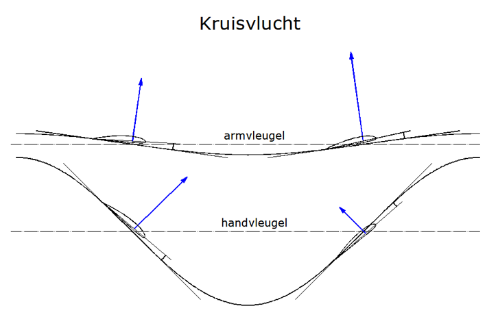
3.2 Werkingsmodus tijdens kruisvlucht
Uitgaand van het hiervoor beschreven vluchtscenario voor de horizontale kruisvlucht is het voordeliger om de totale lift tijdens de opgaande slag te verhogen en het tevens een beetje richting de vleugeltip te verschuiven. Daar wordt n.l slechts een klein beetje lift gegenereerd of zelfs helemaal niets (zie de krachtvectoren in de volgende afbeelding). Maar op deze manier worden het windmoleneffect en zijn arbeidsweerstand verhoogd.
-

- Krachten op de vleugel van een ooievaar tijdens de op- en neergaande slag
van
 Otto Lilienthal

Dat dit voordelig zal blijken te zijn is op het eerste gezicht verwonderlijk. Het windmoleneffect kan nu niet langer worden gebruikt op aandrijfvermogen te leveren in de buurt van de vleugeltip. Zou het niet beter zijn om eenvoudig de slagfrequentie te verhogen?
Overeenkomstig een voorstel van Otto Lilienthal mag de windmolenenergie en de energie van de opgaande slag gebruikt worden in een tweede mogelijkheid. In het begin zal de ornithopter vertragen door de werkweerstand. De daarbij onttrokken kinetische energie kan worden opgeslagen in een veer. De veer zodanig gemonteerd worden dat deze opgespannen wordt tijdens de opgaande slag. De veer ontspant zich weer tijdens de neergaande slag en ondersteunt daarbij de slagbeweging, genereert stuwkracht en zet energie uit de opgaande slag weer om naar kinetische energie van het model.
Een derde mogelijkheid voor het gebruik van windmolenenergie betreft de versnelling van de vleugelmassa in de richting van de opgaande slag. Als de vleugels dan worden vertraagd in de bovenste vleugelpositie door een veer en versneld in de richting van de neergaande slag dan wordt de terugtransformatie van de energie uit de opgaande slag ook op deze wijze tot stand gebracht. Daarbij moet de versnelling van de vleugel niet worden gelimiteerd tot de initiële positie van de opgaande slag.
Gedurende de opgaande slag is in dit soort gevallen geen aandrijving nodig van de slagvleugels. De vleugel levert zelfs dan energie aan de hiervoor genoemde veren. In ieder geval moet de windmolenbeweging wat voor kracht dan ook tegenwerken anders kan er geen lift worden opgewekt bij een bewegelijke losse vleugel.
De energieopwekking van de vleugel bij de opgaande slag is relatief klein. Deze
zal groter worden naarmate het model luchtstromingtechnisch beter is gebouwd
Deze zal groter worden naarmate het model luchtstromingtechnisch beter is gebouwd.
Om bij de opgaande slag veel lift op te wekken is het vleugelprofiel van de binnenste vleugel voorzien van een grote welving.
Zwaan na de start

- De kruisvlucht van een knobbelzwaan vlak boven het water.
- verhoogd en vertraagd (0.4 MB)

-
Het draaien tijdens de neergaande slag is verwaarloosbaar klein.
-
Voor een liftopwekkende opgaande slag wordt de invalshoek van de binnenste vleugelsectie in het begin vergroot. This already starts before the end of downstroke, reaches the maximum near the lower stroke end position and ends approximately at the middle of the wing upstroke. The changing of the angle of attack near the wing root is a characteristic of the flapping flight of birds. It increases the shifting of lift distribution along the semi-span, but is not always as pronounced as in this flight situation (after starting obviously the full cruising speed is not yet reached here).
-
Due to the extended shifting of lift distribution toward the wing root also increases the area of the thrust jet (blast of air) or the thrust. More details about this you can find in het Handboek, bijlage E (Duits) en in het artikel Arrangements of wing tip vortices on flapping wings, versie 4.2, (in het Engels, tweede hoofdstuk, PDF 0.5 MB).
Een dergelijke verandering van invalshoek dicht bij de vleugelwortel is een kenmerk van de vliegtechniek van veel grote vogelsoorten. Het is echter niet altijd zo uitgesproken als hier, kort na het opstijgen van de zwaan. Maar het zal zeker ook een kenmerk worden bij het starten van grote ornithoptermodellen. -
Als gevolg van het drukverschil tussen de boven- en onderkant van de binnenste vleugelsectie heeft de draaibare buitenste vleugelsectie de neiging om naar boven te draaien. Dit wordt waarschijnlijk tegengegaan door de negatieve druk bij de vleugeltip.
-
De sturende binnenste vleugelsectie stopt in de bovenste slagpositie tot het einde van de opgaande slag van de buitenste vleugelsectie is bereikt.
-
Als de buitenste vleugelsectie is opgetrokken dan wordt de opgaande slag alleen nog beïnvloed door de lift.
-
Tijdens de opgaande slag neemt de relatieve sterke draaiing van de vleugel af. Dit kan vanuit de kijkrichting de verkeerde indruk wekken dat de vleugelverdraaiing tijdens de opgaande slag van richting verandert.
Deze fotoserie is mij verstrekt door
A. Piskorsch.
Als gedurende de opgaande slag de totale lift opgewekt wordt dan werkt de slagvleugel inderdaad als een tweetakt motor in de liftrichting, maar wanneer dit gezien wordt in de vliegrichting dan is deze wisselend omgekeerd. Niettegenstaande dat, wordt de windmolenenergie gebruikt voor opwekking van stuwkracht - uiteraard onder aftrek van de gebruikelijke verliezen als profielweerstand en geïnduceerde weerstand. Maar deze nemen ook toe bij liftopwekking.
Onafhankelijk van de versnellingsrichting dient de vliegsnelheid constant gehouden te worden. Hieraan draagt een hoge slagfrequentie en een hoge modelmassa zeker bij.
Gedurende zulke kruisvluchtconfiguraties van de opgaande slag wordt de lift groter dan bij een geleidelijk toenemende klimvlucht. Los van opwekking van trekkracht kan lift ook gedurende de neergaande slag worden opgewekt. Daarvoor moet de liftverdeling verschoven worden naar de vleugelwortel en in verhouding lager worden afgesteld.
-

- Diagram 4
- Liftverdelingen voor een kruisvlucht met een relatief laag gemiddeld moment aan de slag-as

Alles bij elkaar genomen wordt de liftverdelingen van beide werkcycli bijna gelijk aan die van de liftverdeling tijdens de zweefvlucht. Deze wordt beter benadert naarmate het vliegtuig stromingstechnisch is geoptimaliseerd. Er is dan minder stuwkracht nodig. verder zal hierdoor de geïnduceerde weerstand tijdens de neergaande slag aanmerkelijk minder zijn.
Waarschijnlijk is het genoeg de lift slechts een beetje langs de spanwijdte te verschuiven, zonder de afmeting te wijzigen, richting de vleugelwortel tijdens de opgaande slag en richting de vleugeltip tijdens de neergaande slag. Daarvoor is echter een verdraaiing van de vleugelwortel vereist.
Meeuw tijdens kruisvlucht

- verhoogd en vertraagd

Gedurende de gehele neergaande slag en aan het begin van de opgaande slag neemt de invalshoek in het midden van de halve spanwijdte toe.
Uit een 16 mm film van
A. Piskorsch
De voordelen van een slagvleugel die in twee tegengestelde richtingen werkt bij de op- en neergaande slag ligt met name in de opwekking van dezelfde hoeveelheid lift. De verticale beweging van de romp is tijdens de horizontale vlucht vrijwel geheel verdwenen.
Alles bij elkaar genomen geldt dat een effectieve constante kruisvlucht alleen worden gerealiseerd wanneer de stuwkracht naar voren is gericht en niet omhoog. Daarbij is de slagfrequentie beduidend lager dan bij de volgende manier van vliegen.
3.3 Sterk stijgende klimvlucht en bidvlucht
Maar in vergelijking met een helikopter kan de gewichtskracht gedurende de vlucht
door een krachtstroom die omlaag gericht is en een trekkracht die omhoog gericht
is. Dit heet Vliegen met stuwkracht
. Daarbij wordt de
opgaande vleugelslag praktisch alleen verricht door de aandrijving. In principe
staat gedurende de onversnelde vlucht de stuwkracht altijd loodrecht op het vlak
van de vleugelslag en kan deze worden aangepast door de instelhoek.
-

- Kleine vogel
tijdens nadering

Als de stuwkracht precies in de vliegrichting wijst, dan is er sprake van of zuiver vliegen met stuwkracht (verticale klimvlucht) of een zuivere vlucht met lift (horizontale vlucht). Bij instellingen tussen deze uitersten in en gedurende niet te langzame horizontale beweging wordt de de gewichtskracht uitgebalanceerd door de door de vleugel geleverde lift- en stuwkracht. Deze gemengde vormen worden toegewezen aan het z.g. vliegen met stuwkracht.
De grondstart van een ornithopter, hangen op één plaats, sterk stijgende vlucht en de langzame horizontale vlucht zijn alleen mogelijk met het vliegen met stuwkracht. Hier tegenover staat dat een snelle horizontale vlucht kan worden gerealiseerd met beide methoden (met een duidelijk onderscheid in de benodigde hoeveelheid vermogen). Relatief snelle horizontale vluchten en kruisvluchten kunnen alleen worden gerealiseerd op basis van vliegen met lift.
In de praktijk fungeert de hoek van het vlak van de vleugelslag als een identificatie criterium voor de vliegmethode Tijdens de horizontale vlucht is deze vertikaal ten opzichte van de vliegrichting. Als dit aanzienlijk afwijkt (meer dan 10 graden) dan wordt gevlogen met stuwkracht. Verder geldt dat wanneer een grote vleugelverdraaiing wordt geconstateerd waar bij een normale vlucht slechts weinig vleugelverdraaiing optreedt (In ieder geval bij hoge Reynoldsgetallen). Ook een relatief hoog benodigd vermogen wijst in deze richting.
Verder zijn de poten van de vogels, in ieder geval bij de grotere, niet volledig
naar achteren gestrekt als ze met stuwkracht vliegen. Ook is het lichaam niet
volledig in de vliegrichting gericht (![]() R. Demoll 1930). In publicaties van onderzoeken
met betrekking tot de vogelvlucht wordt vrijwel nooit gewezen op deze twee van
elkaar afwijkende vliegmethoden. Het hoge vermogen dat benodigd is gedurende de
langzame vlucht wordt in het algemeen alleen toegeschreven aan de toegenomen geïnduceerde
weerstand (b.v. zie externe link 2).
R. Demoll 1930). In publicaties van onderzoeken
met betrekking tot de vogelvlucht wordt vrijwel nooit gewezen op deze twee van
elkaar afwijkende vliegmethoden. Het hoge vermogen dat benodigd is gedurende de
langzame vlucht wordt in het algemeen alleen toegeschreven aan de toegenomen geïnduceerde
weerstand (b.v. zie externe link 2).
-
")
- A. Pénaud (1872)
")
Vliegen met stuwkracht wordt al toegepast bij een technisch model sinds het begin van van let luchtvaarttijdperk. Maar het horizontaal vliegen van grote en zware ornithopters vraagt aanzienlijk meer meer vermogen dan wanneer alleen met lift wordt gevlogen.
Otto Lilienthal maakte al een duidelijk onderscheid tussen deze twee manieren van
de vogelvlucht met behulp van vermogen en heeft ook de enorme hoeveel Werkbelasting
aangegeven die nodig is bij een langzame vlucht.
4. Hoe grote vogels vliegen
(in het Engels)
4.1 Vliegen met sterk fluctuerende lift
-
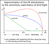
- Vermoedelijk, bij benadering, verloop van de lift langs de spanwijdte,
overeenkomend met de algemeen gebruikte beschrijving van de vlucht van vogels. -

- Grootte van de liftkrachten op een slagvleugel die bij de gebruikelijke beschrijving van een slagvlucht met sterk fluctuerende lift voorkomt.
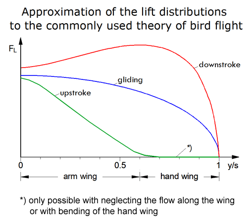

In the commonly used theory of bird flight, a lot of lift and thus also a lot of thrust is generated in the outer wing area during downstroke.. Thus, the outer wing area is guided upwards without significant power delivery. This is especially to avoid working drag during upstroke (please see adjacent diagrams and the description of the commonly used theory of bird's flight at external link 3). About a turning of the wing root or other measures to increase the lift in the arm wing area during the wing upstroke is nothing reported. The lift at the wing root is accordingly small.
This theory describes a distance flight with strong fluctuating lift and orresponding carry force. However, the up and down swinging of the bird's body is observed only rarely. It also occurs only during distance flight. The cruise flight is generally performed only with approximately constant lift (please see Bewegingsovergang bij vogels, chapter 4. The common theory makes no difference between these two types of flight, that is with or without bending of the hand wings.
With fluctuating lift, a vortex ring is created, especially during downstroke. This floats away to the rear on upstroke. Thus, in addition to the wing tip vortices a series of vortex rings formed along the flight path. The starting vortex generated at ring formation increases the induced drag and thus the required drive energy. Therefore, such vortex rings should be avoided by keeping the lift as constant as possible.
For ornithopters it is easier to realize the method with strong fluctuating lift, as described in the commonly used physics of bird's flight. There is then no need to turn the wing root or to take other measures to increase lift in the arm wing area during wing upstroke. But then you must relinquish about half of the possible lift capacity and compensate for this by flying at a higher speed. Thus, the carry force is low in this mode of flight. This is certainly one of the reasons why man-carrying ornithopters have not yet been able to get off the ground (please see also Lift during wing upstroke, version 10.1, in het Engels, PDF 0.9 MB).
When a seagull is flying with a strong headwind, her whole body swing up and down, something like at the Meeuw in een vlagerige wind (animation, 0.5 MB). During its motion downward, in this way the inflow at the wing root is more from below. This creates thrust, please note thrust at the wing root. Besides, this increases the lift there. However, this was not yet investigated in closer detail.
4.2 Vliegen met ongeveer constante lift
-
- Basisprincipe van het genereren van lift en stuwkracht tijdens de vlucht van vogels
In the adjacent diagram, E. v. Holst (1943) (PDF 3.2 MB) sketches how, in principle, an optimal thrust generation can occur in birds flying with a large rate of advance. His thought experiment will be slightly modified here. The shiftable wings shown here are not really to be moved, but merely to embody the shiftable position of the centre of lift.
-

- Traject van het liftcentrum (Lc) langs de spanwijdte van een slagvleugel

At the upper reversal point of the stroke motion the lift centre is shifted towards the wing tip and at the bottom point to the wing root. Seen over a whole stroke period, while maintaining the lift L, the thrust T is greater on the downstroke than on the upstroke. The shift of lift is achieved by the aerodynamic interaction of the arm and the hand wing (e.g. the wing root is turned during upstroke). With this method, the Continuous-vortex gait will be realized.
-

- Stuwkrachtgenerering op de slagvleugel tijdens het vliegen met ongeveer constante lift

With this ingenious trick of nature, it is possible to generate much lift also during the upstroke and nevertheless, seen over an entire operating cycle, a thrust generation is made possible. Since birds are very streamlined shaped, a relatively small shifting of lift is sufficient for them during cruise flight (see for example the position of the centres of pressure in diagram 4, above).
Stork in cruise flight

- Slower and augmented

In contrast to small birds, here the wing feathers are spread out during up- and downstroke.
The nodding motion of the bird's body causes an increase in the angle of attack on the wing root, especially at the beginning of the wing upstroke.
From a 16 mm movie by
A. Piskorsch
-

- Liftverdelingen, tijdens de opgaande slag met de grootst mogelijke lift in het armvleugelgebied, aan een rechthoekige vleugel met het profiel CLARK-Y

Professor Jeremy Rayner has researched the flight of birds at the University of
Leeds (England). Thereby he also already largely described the way of flying with
constant circulation or constant lift (zie article Vertebrate
flapping flight mechanics and aerodynamics and the Evolution of flight in bats
in ![]() Nachtigall W. 1986, BIONA-report 5).
He emphasizes the importance of this gait and sees its strong experimental confirmation
in the flow visualization experiments with a kestrel in fast flight by G. R. Spedding
(et.al., 1984, 1986, 1987). The resulting image of the Continuous-vortex
gait show a non-planar pair of vortices with variable mutual distance, closely
following the wing. According to J. Rayner, the starting point of the tip vortices
at the trailing edge of the wing moves bidirectionally between the wrist joint
and the tip of the wing. Approach vortices are not visible (please look at externe
link 4).
Nachtigall W. 1986, BIONA-report 5).
He emphasizes the importance of this gait and sees its strong experimental confirmation
in the flow visualization experiments with a kestrel in fast flight by G. R. Spedding
(et.al., 1984, 1986, 1987). The resulting image of the Continuous-vortex
gait show a non-planar pair of vortices with variable mutual distance, closely
following the wing. According to J. Rayner, the starting point of the tip vortices
at the trailing edge of the wing moves bidirectionally between the wrist joint
and the tip of the wing. Approach vortices are not visible (please look at externe
link 4).
-
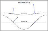
- Grootte van de liftkrachten op een slagvleugel tijdens de distancevlucht, met ongeveer constante lift en tijdens de opgaande slag met schuine handvleugel.
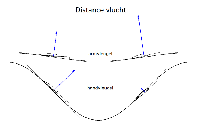
If the bird flies in distance flight with approximately constant carry force, the lift force at upstroke and downstroke has in principle the magnitude ratios as in the adjacent diagram. The large lift at upstroke on the arm wing is achieved by its change in shape when it is angled. This is supported by a strong bending of the hand wing, possibly combined with a turning of the wing root. Sometimes the distance flight is also executed with strongly fluctuating lift. It then can be recognized by its oscillating trajectory. This is especially the case in slow flight and/or with high thrust requirements.
The large lift on upstroke is only possible, because of the birds strongly cambered high-lift profiles in the arm wing area (zie het volgende hoofdstuk 4.3). Together with the large wing depth, much more lift can be produced there, than with the hand wing during downstroke. As a result of the bending, the hand wing can operate with very little lift, even though it is directly adjacent to the high lift of the arm wing. With its winglet effect, the bend reduces the outflow of lift from the mid-span in the direction of the wing tip.
-
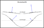
- Grootte van de liftkrachten op een slagvleugel tijdens de kruisvlucht, met ongeveer constante lift en tijdens de opgaande slag met gestrekte handvleugel.
In horizontal cruise flight, the positive thrust on downstroke is only sufficient to compensate the negative thrust on upstroke. No thrust remains for a climbing flight. The advantage of this way of flying is the high performance over long distances.
For the large lift in the arm wing area, the shape changes in the arm wing are probably sufficient in this case. A bending of the hand wing is barely recognizable.
If one compares in this context the calculated examples in the article Flapping wings with and without wing turning (in het Duits, PDF 0.9 MB) it confirms that equable and uneven lift have preferences. This is also the case there, because the size of the lift during wing upstroke is determined in particular by the choice of lift distribution. The flight mode with strongly fluctuating lift offers advantages for climb flight (see example 1, with c_Γ1=0) and the flight mode with relatively constant lift for long-distance flights (see example 10, with c_Γ1=5 or 6). But here, too, the general rule applies, what is good for the lift is detrimental to the thrust and vice versa.
Krachten in een slagperiode
-

- Slagvlucht
-

- Vogelvlucht


Slagvlucht
met sterk fluctuerende lift, in overeenstemming met de conventionele beschrijving
van de slagvlucht. Bij vogels wordt de bijbehorende pendelbeweging van het lichaam
echter zelden vastgesteld.
Van de afgebeelde resultante R
kunnen het dragende kracht en de stuwkracht
worden afgeleid (hier niet afgebeeld). Pendelbewegingen van de romp ten gevolge
van liftschommelingen worden hier verwaarloosd.
Vogelvlucht
met constante circulatie, overeenkomend met de Continue-vortex
gang
Bij deze gang zijn er geen wervelringen in het wak van de vleugel. Bijgevolg werkt het met een constante grootte van de circulatie en dus ook met een constant lift. Dit werd voor de presentatie mathematisch verdeeld over de arm- en handvleugels, met passende liftverdelingen (pols op 0.6 van de half spanwijdte).
In dit example resulteert dit in een licht variabel draag kracht en betrekkelijk weinig stuwkracht. In de slageindposities is de lift kracht het grootst, met elliptische liftverdeling. Weerstand en pendelbewegingen van de romp werden daarbij niet in rekening gebracht. To fly with constant carry force it is certainly necessary to work with slightly fluctuating lift.
A further clarification of the different theories of bird's flight is possible, in particular by measurements on technical flapping wings in wind tunnel. Thereby the effects of various twistings and turnings on the lift distributions along the span should to be researched. Also, the behaviour of the wing tip vortices and the downward bending of the outer wing-section are interesting.
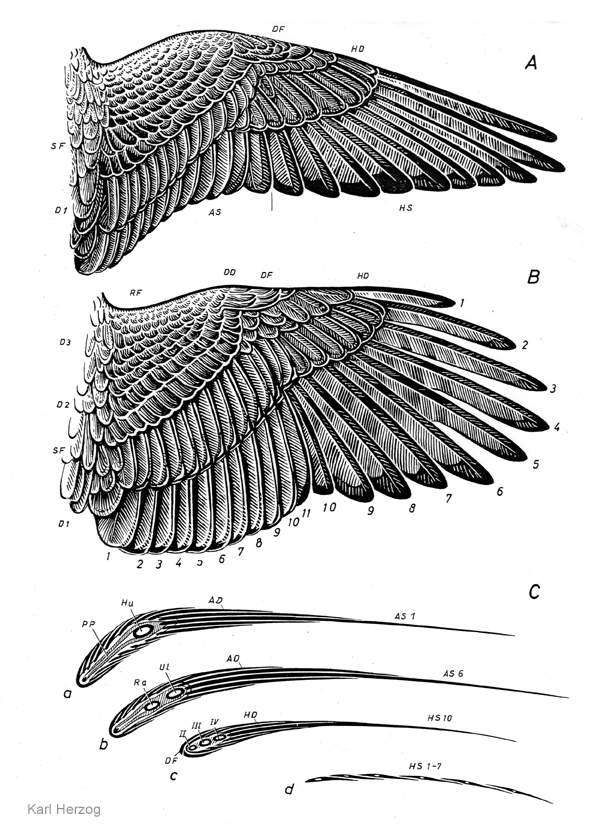
4.3 Anatomische vormveranderingen van de armvleugel
-
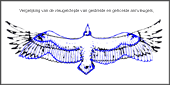
- Vergelijking van de vleugeldiepte van gestrekte en gehoekte armvleugels, respectievelijk
bij de neergaande en opgaande vleugelslag, bij een gier (images
by
Heinrich Hertel)
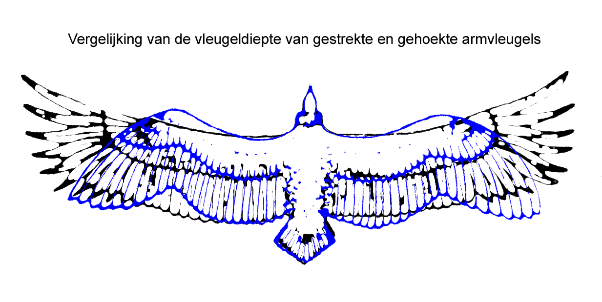
In addition to turning of the wing, birds have other possibilities to change the size of the lift near the wing root. When angling the arm wing, for example, they can use the tendon of the forward flight skin (propatagium) to increase the wing depth, mainly in the part of the arm wing close to the body. Thereby they also increase the lift there (please see adjacent picture, especially the right wing-side). Birds also have these design possibilities during wing upstroke, whether with the hand wing extended or bent downward.
Also, because the forearm is mostly longer than the upper arm, the wrist is shifted forward when the arm wing is angled. This changes the direction of pull correspondingly along the tendon. In this way, the wing depth increases, especially near the elbow, and thus the lift along the whole arm wing. This shifts the lift of the whole wing more towards the mid-span. All this is also the case with the wing upstroke.
However, birds can also configure the arm wing in a different way. This can be
recognized on the left wing of the blue bird. There, the wing depth is kept almost
constant along the whole arm wing. The arm wing is more stretched. The way of
flying of the blue bird is described by ![]() Heinrich Hertel as
Heinrich Hertel as flat gliding
. Obviously
it is a curved flight to the right. The black vulture soaring in the thermal,
on the other hand, curves to the left with inversely changes of both arm wings.
Unlike in technical gliding, here changes also take place on the inner part of the wing during the curving flight. On the inside of the curve, the incoming flow velocity is lower than on the outside. This is compensated by increasing the wing depth on the arm wing. In terms of induced drag, this is certainly better for stabilizing the curving flight, than corresponding changes to the outboard ailerons.
-

- Anatomie van een vogel-vleugel in de gestrekte toestand, spierstelsel bovenaanzicht
( by
Karl Herzog, 1968)

In the adjacent picture, each of the tendons (11a and 12a) of the fore and aft flight skins is held at the wing root by a small pair of muscles (11 and 12). They can vary the direction and the tension of the tendons within narrow limits. Changes in the tension or direction of a flight skin tendon affects lift in the arm wing area. However, it is largely unknown how and in which flight situations these muscles are used together with the arm extensor (9) and the arm flexor (10). For example, also in the enlargement of the wing depth. In flight, when the wing is slightly stretched as shown in the adjacent picture, the tendon of the front flight skin is sagged backwards in the middle of the arm wing (please see wing of a pigeon). Birds that also soar can stretch the arm wing a little further.
Birds, however, can stretch the arm wing a little further against the pull of the tendon of the forward flight skin. Supported by the resulting strong pull of the tendon on the thumb knob of the metacarpal bone, the hand wing pivots forward a little. The elbow approaches the leading edge of the wing and the outer primary feathers will be spread. In the case of the soaring vulture, there is hardly to be seen any deflection of the tendon to the rear.
For the tension of the rear flight skin tendon, there are mainly determining the pull directions and pull forces of all muscles pulling on the upper arm bone (humerus). In flight, when the wing should not be angled so strong, the tendon is always kept stretched tight. Stretching and angling of the arm wing than will be realized almost nearly solely with the forearm. To increase the wing depth at the elbow, the humerus is pulled back just a little, probably with the muscle of the tendon of the rear flight scin. Only when the arm wing should be angled extremely during upstroke, or when balancing, the humerus will be directed more to the rear.
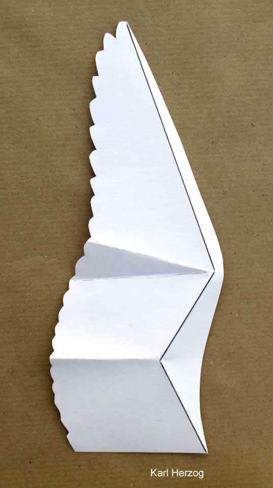
It would be interesting to know how the height position of the elbow relative to the connecting line between the shoulder and wrist changes when it is angled. The height position can be mechanically coupled with the angling of the arm wing. The position of the elbow determines the upper corner point of the forward downward inclined elastic flight skin (please see 3D-shape of the bird wing by K. Herzog). If the elbow moves upward, for example, it also pulls the front tendon with the flight skin in this direction. This is especially the case when the tension of the tendon will be loosened. This increases the angle of attack.
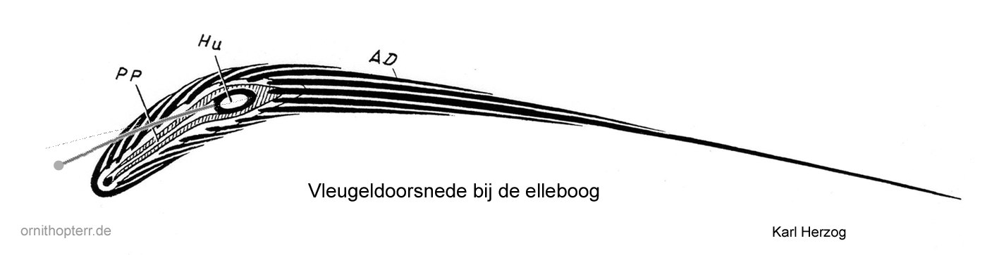
-
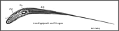
- Vleugeldoorsnede bij de elleboog van een havik
vleugel
B
met onder een gestrekte armvleugel in passive state.
The approximate position of the front flight tendon in distance flight at upstroke is indicated.
With the elevation of the elbow, also changes the size of the airfoil camber. With a larger profile camber, larger lift coefficients are possible. And when the wing depth is increased by the front flight skin, the elbow shifts to the rear in relation to the airfoil depth. With it, the maximum of the airfoil camber also shifts.
The camber of the arm wing profile is elastic along the wing depth, particularly in the area of the front flight skin. This is also the area with the biggest pressure difference between the upper and lower side of the profile. The flight skin is thus aerodynamically pulled forward-upwards in flight. It is then curved upwards and pulls the fore tendon upwards with it.
The front tendon is bent even more forward in the middle during the upstroke than with stretched wing (please see image vergelijking van de vleugeldiepte). Thereby the e movement of the tendon upwards is facilitated there, and even supported by the pull forward. In addition, the wing depth is increased.
For anatomical reasons, the tendon will then probably be placed a little below the extension of the longitudinal axis from the oval of the displayed bone (please see the above image). This reduces the oversized camber of the profile that is displayed. At the same time, it increases the angle of attack. However, also the rear flight feathers bend slightly upwards in flight. This is aerodynamically advantageous for the wing upstroke. So, the flow does not stall on the underside of the profile. As a result of the angling of the arm wing during upstroke, the angle of attack in the area of the arm wing automatically becomes a little larger. With the help of the tension of the tendon respectively the angling of the forearm this effect can be varied.
-

- Vulture. Variable wing plan: Sailing-Gliding
(images
by Heinrich Hertel)

The adjacent image is to illustrate in particular the possible change in size of the wing area. This is associated with a change in the flight speed.
However, the image also shows that when the arm wing is increasingly angled, the pull direction of the tendon of the front flight skin points very strongly forward in the area of the elbow.
Due to the strong sweep of the forearm, the lift there is shifted in the direction of the elbow as a result of the oblique blowing. This promotes the concentration of lift in the centre of the span during upstroke.
A similar, roughly approximated change in angle of attack on the arm wing can also be achieved on a technical Gewrichts-slagvleugel wing. A change in the angle of attack on the arm wing can also be achieved without rotating the wing root. To do this, part the rear spar of the arm wing approximately in the middle. Both parts of the tie bar must then be reconnected with a joint. If you now control the angle of attack of the wing rib there, the angle of attack of the whole arm wing changes from there , strong in the middle and weakening at the ends. This helps in the aerodynamic interaction of the arm and hand wing when the lift in the hand wing becomes smaller at upstroke.
5. Externe Links
- Tips and observations of bird flight by Brendan Body:
http://www.brendanbody.co.uk/flight_tutorial/index.html - Bret W. Tobalske, Biomechanics of bird flight (2007):
http://jeb.biologists.org/content/210/18/3135.full
Also look at the reference list of this commentary. - Nathan Chronister explains very concrete the theory of the flight of birds
which is commonly used today by biologists.
https://www.ornithopter.org/birdflight/flap.shtml - Tyson L. Hedrick, Bret W. Tobalske and Andrew A. Biewener (2002)
Estimates of circulation and gait change based on a three-dimensional kinematic analysis of flight in cockatiels (Nymphicus hollandicus) and ringed turtle-doves (Streptopelia risoria)
please look at Fig. 1. AContinuous-vortex gait
http://jeb.biologists.org/content/205/10/1389.full